When Water has to flow “Uphill” –Drainage of the Noise Protection Galleries on the A 96
As part of the six-lane widening of the German autobahn A 96 between Oberpfaffenhofen and Germering-Süd, two noise protection galleries are being built for the towns of Gilching and Germering. The drainage of these gallery structures is in accordance with the guidelines for tunnels. In order to be able to securely collect surface water, extinguishing water and water from incidents, a modified drainage system of slot channels with internal fall is being used.
Widening of the A 96
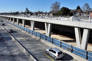
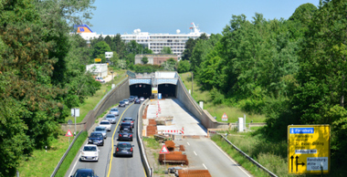
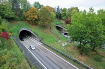
A large part of the overall costs for the almost 9 km long stretch of the A 96 is for the widening from four to six lanes. This includes the laying of an asphalt surfacing of porous asphalt (with a noise reduction effect of 5 dB (A)) and construction of the so-called noise protection galleries (Fig. 1). These are designed like a half tunnel and closed toward the housing in order to protect the inhabitants of the towns of Gilching and Germering from the increased traffic noise in the future. In Gilching, a gallery about 520 m long is being built while traffic continues to flow, and the gallery in Germering is 965 m long. Both will be completed in 2020.
Galleries like those on the autobahn A 96 are considered equivalent to tunnels with regard to drainage. In the design on the A 96, potential incidents were the first consideration, more important than the discharge of surface water at the portal and water carried in by vehicles. In order to be able to securely and rapidly collect surface water, extinguishing water or any fluids escaping in the event of an accident, a modified drainage system is used. This tunnel channel complies with all the requirements of the RABT and the ZTV-ING.
The Requirements of the RABT and ZTV-ING
The German guidelines for the equipment and operation of road tunnels, abbreviated RABT, are the basis for the high level of safety in German tunnels. They lay down requirements for the prevention of incidents and the protection of people in a tunnel. Comprehensive protection is provided by constructional measures concerning the tunnel equipment for lighting, ventilation, water and energy. The layout of safety equipment and the materials used are important. The RABT is primarily concerned with the equipment and operation of road tunnels. The additional technical conditions of contract and guidelines for engineered structures, abbreviated ZTV-ING, describe requirements for construction in the widest sense, including requirements for materials, material systems and construction elements.
Drainage Systems in Tunnels
Special requirements also apply to the materials of drainage systems in tunnels. For example, in addition to uncontaminated surface water, flammable and hazardous fluids must also be collected and drained to a closed system as rapidly as possible. The ZTV-ING – Part 5 Tunnel building states in this regard:
The following waters and other fluids are to be drained by the drainage system after completion of the tunnel:
● formation water, if the tunnel has not been designed to resist water pressure,
● rainwater,
● washing water,
● extinguishing water and
● other fluids, such as mineral oils and chemicals, which come from transported goods. [1]
The ZTV-ING – Part 5 also lays down the following requirements:
● The water and other fluids are to be collected in the main tunnels in a slot channel at the lower edge of the carriageway. This is to be connected to the longitudinal drain at the most every 50 m through a siphon or a baffle shaft. In sections of tunnels with little gradient, the distance between drainage shafts must be reduced. The slot channel is to belong to class D400.
● For fire safety reasons, the slot channel must have a bulkhead behind every branch to the main drain. The minimum slope of the slot channel is 0.5 %.
● For the longitudinal drainage pipe the minimum diameter is 300 mm, the minimum slope is 0.5 %. [2]
Polymer Concrete as a
Construction Material for Drain Systems
With version 03/12 of ZTV-ING – Part 5 Tunnel building, slot channels of polymer concrete are approved. Polymer concrete is thus equivalent to concrete as a material for use in tunnels. It is stated in ZTV-ING – Part 5:
● DIN EN 1433 and DIN 19580 are applicable for slot channels. They are to be assigned to exposure classes XF4 and XD3 according to the DIN specialist report “Concrete”.
● Slot channels of concrete and polymer concrete are approved. [3]
Regarding utilisation of slot channels of concrete and, for example ACO polymer concrete, the comparison of the two materials in practice is very interesting. Polymer concrete shows essential advantages. With a comparable density, polymer concrete shows much higher strength values with lower weight. Polymer concrete is watertight and frost damage can be ruled out. The smooth surface due to a water benetration depth of 0 mm permits water and dirt particles to run off quickly. Polymer concrete is also resistant against aggressive media without any additional coating.
For the production of drainage channels for use in tunnels, ACO uses a special polymer concrete mixture, which corresponds to all requirements of the classification of a non-flammable construction material. Using the most modern production technologies, this polymer concrete fulfils the fire class A2-s1, d0 “non-flammable” according to DIN EN 13501-1.
Tunnel Channels with Internal Fall
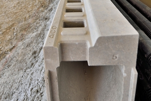
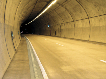
Normally there is a longitudinal slope of 0.5 % in road tunnels due to the tunnel gradient, and the maximum distance of sump units of 50 m can be used. Only at high or deep points, for housings in inner-city applications or the so-called galleries is the gradient sometimes less than 0.5 %, in which case tunnel channels with invert slope have to be used – which was the case for the two galleries at Gilching and Germering on the A 96 (Fig. 2).
According to RABT and ZTV-ING, a requirement for the drainage of tunnels is that in case of an incident, a capacity of at least 100 l/s is needed. The maximum distance of sump units can also only be 50 m, with a minimum slope of 0.5 %. Furthermore, the design of the siphon must hinder the propagation of flames [2]. Considering these requirements, the ACO Drain tunnel channel system was extended for the drainage of the two galleries. For the Gilching and Germering gallery projects, the new tunnel channel ACO Drain Monoblock T 200 V with 1 % invert slope was used. This made a longer distance between shafts possible, which reduced the total investment for the clients.
12 channel types with fall are available in 2 m lengths, which can be laid against the surface gradient since the effective slope is > 0.5 % to the sumps. In this way 24 m of channel can be laid each side of the baffle shaft, which reduces the total number of shafts. Furthermore, the nominal width and thus the overall width of the construction element could be reduced to 200 mm while still ensuring the hydraulic capacity.
The programme was supplemented in this version with side openings to drain the porous asphalt, which was used for the surface of the portal area of the gallery. Inside the gallery, a concrete surface was used, so that the channels could be laid with the standard construction method.
Baffle Shaft with Inlet from both Sides
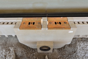
The baffle shaft is the transition element and acts as a bulkhead. This separates the closed drainage system, the main drain pipe, from the open drainage system of the tunnel channels. The integrated baffle acts as a siphon. A minimum fluid level in the shaft base and the baffle act as a fire bulkhead against flames propagating to the longitudinal drainage pipe and as an odour trap. The baffle shaft with inlets on both sides for the modified channel construction is a new development (Fig. 3). For optimal hydraulic characteristics, a shaft with flow-optimised discharge haunch was developed and a patent has been applied for. By halving the number of shafts and covers for cleaning and inspection, not only the investment was reduced but the operational and maintenance costs could be minimised.

