Ways to Reduce CO2 in Sprayed Concrete for
Tunnel Construction
Sprayed concrete construction in double-shell lining is a CO2-intensive construction method for tunnel structures. This article explains the ecological impact of concrete in underground construction and provides options for using this material responsibly and in a climate-friendly way – particularly in terms of planning and concrete technology.
1 Introduction
A growing global commitment to environmental protection on one hand, progressive resource exploitation and climate-related natural disasters on the other – the topic of sustainability is moving more sharply into the focus for society. Faced with the looming climate crisis, awareness of sustainable development has come to the fore in the early 21st century and has, by now, made its way into the construction industry. Conventional building construction is already experiencing an increasing demand for ecology-friendly building materials and efficient construction methods. In tunnel and underground construction, however, the issue of sustainability continues to play a subordinate role. But there are various ways to reduce the carbon footprint of projects during the planning phases in this material-intensive sector, in some cases significantly.
The increasing urbanisation of the world‘s population is also affecting us – in the form of increased construction activities and an accompanying rise in greenhouse gas emissions. According to forecasts, by 2050 around two thirds of the world‘s population will live in cities and will be dependent on a corresponding urban infrastructure.
This means a decrease in individual transport and a necessary steady growth of public infrastructure systems – also underground. Modern metro systems contain a huge number of entries, transport hubs, intersecting tunnels, access and escape tunnels, shafts, station caverns, ventilation facilities and more. As these structures are usually constructed by conventional tunnelling methods, materials that easily adapt to changing cross-sections are predominantly used for the lining.
Scepticism About the Durability of
Sprayed Concrete
Sprayed concrete is the preferred material for initial support due to its ease of handling. Despite decades of positive experience with this construction material [1], sprayed concrete is still only recognised as a temporary support material in most cases. Its use on a larger scale for the inner shell of tunnel structures is still not common practice. This is due in particular to scepticism about the durability of sprayed concrete. The consequences are often over-dimensioning and an associated use of more material, which has a negative impact on the CO2 balance of the construction project. This article therefore explains in more detail the potential for reducing the carbon footprint of new tunnel projects built using sprayed concrete as support material.
2 CO2 Footprint of Concrete
and Sprayed Concrete
With more than 14 billion cubic metres used per year, concrete is the most important mass construction material of our time, and it is impossible to imagine modern civil engineering and tunnel construction without it [2]. However, the cement contained in it poses a climate problem, because the production of the clinker for the cement releases enormous amounts of – previously chemically bound – CO2 during the calcining process. With greenhouse gas emissions of around 800 kg CO2e/t of clinker, cement is responsible for up to 91% of the CO2 footprint of concrete [3] and worldwide for about 8% of anthropogenic CO2 emissions. That is four times as much as that produced by the entire global air traffic. The ecologically and economically efficient use of clinker in concrete and sprayed concrete is therefore key to improving the life cycle assessment of tunnel structures.
Since sprayed concrete usually has a very poor life cycle assessment due to the high proportion of Portland cement in the mix, potential for optimisation should be considered as early as the planning stage. Even minor changes in the mix and an increase in the clinker efficiency of the building material can lead to a significant improvement in the life cycle assessment of the entire structure, as large-scale tunnelling projects require enormous quantities of construction material.
Cement Is Responsible for 66% of the CO2 Emissions From the Brenner Base Tunnel
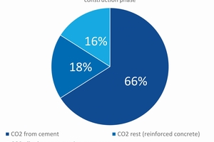
Reference [4] illustrates the correlation between cement use and carbon footprint with the example of the Brenner Base Tunnel project (220 km tunnel in total, NATM and TBM). Here, the share of CO2 emissions from cement production is responsible for 66% of the total emissions during the construction phase. All other concrete components and their production only account for 18%, while the remaining efforts and processes, such as the energy required for the operation of the TBM, fuels, sealing materials and the like, only account for 16% (Fig. 1).
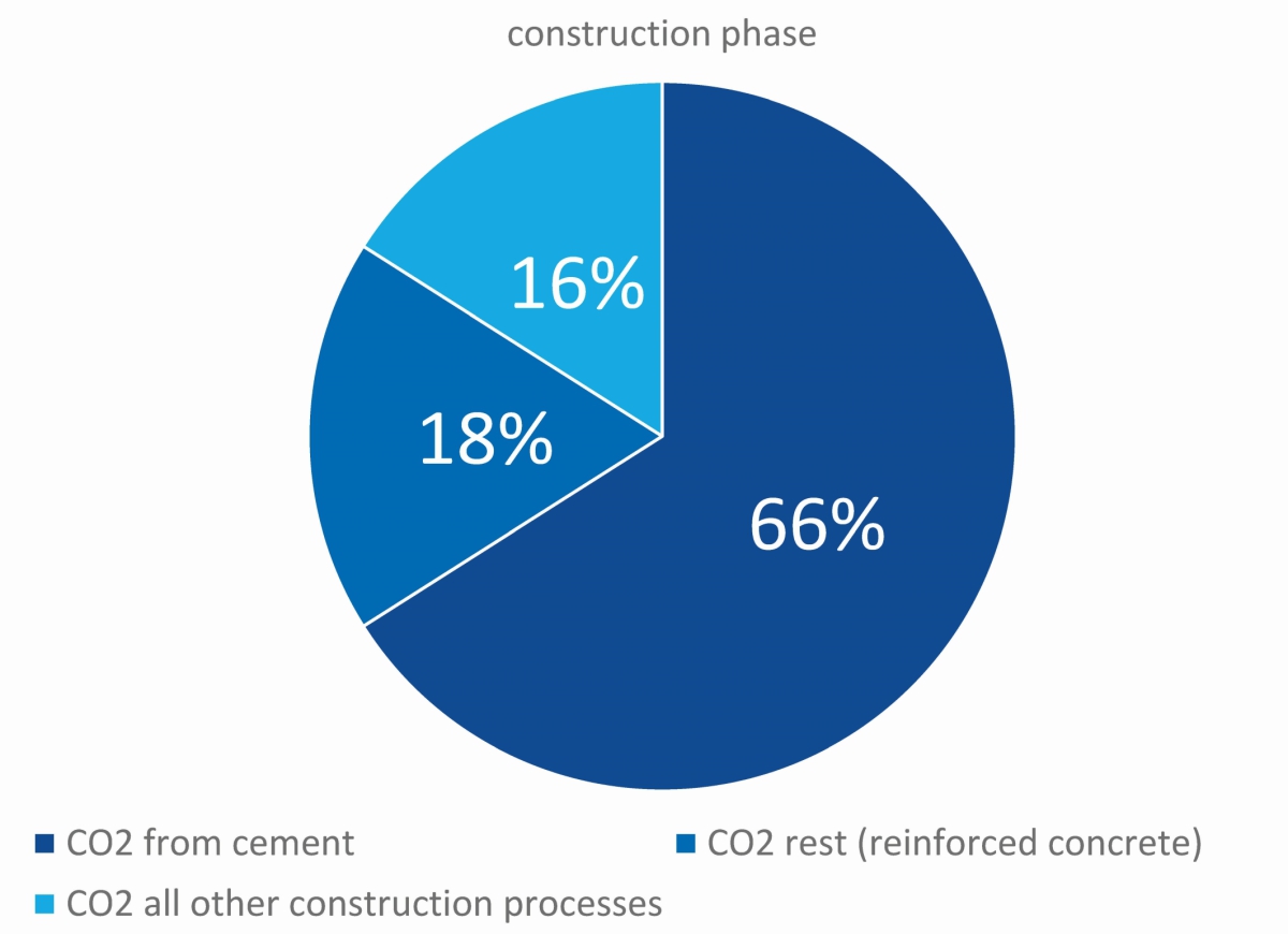 1 | CO2 emissions resulting from the construction of the Brenner Base Tunnel
Credit/Quelle: [4]/Master Builders Solutions
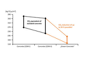
To reduce the greenhouse gas emissions of a concrete mix, clinker-efficient composite cements as well as pozzolanic, latent hydraulic and/or inert cement substitutes and fillers (e.g. granulated blast furnace slag, limestone powder, etc.) can be used. Figure 2 shows the CO2 saving potential of these more sustainable concretes. Since the so-called eco-concretes present some challenges regarding their workability and mechanical properties, extensive concrete technology know-how and the optimal coordination of the admixtures used in such systems are indispensable to fulfil the necessary requirements for consistency, early strength and durability.
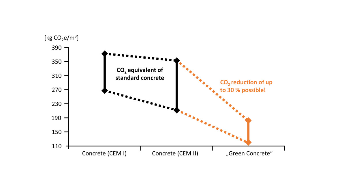 2 | Potential for greenhouse gas reduction by using ecologically optimised concretes
Credit/Quelle: [5]/Master Builders Solutions
The above considerations on the life cycle assessment of concrete, and the fact that the clinker in the cement dominates the CO2 emissions of concrete underground construction, inevitably lead to the question of whether the double-shell lining and the assumption that sprayed concrete is not durable should remain the state of the art. Some considerations about that question are given below.
3 Sprayed Concrete as Permanent Lining
Nowadays, sprayed concrete is mostly produced with computer-controlled mixing plants and applied using state-of-the-art spraying equipment. The quality of the application has continuously improved in recent years due to upgraded machine technology and high levels of qualification among nozzle operators. The cement and chemical industries have also had a significant influence on the success of sprayed concrete construction, since the available solutions and materials have become increasingly efficient. Tests on tunnel structures built in the 1970s and 1980s in Austria [1, 6] revealed unexpected results: the sprayed concrete retained its performance even after 40–50 years, although it was originally designed and installed only as a temporary support.
The actual strengths achieved today are higher than the design strengths, moreover, the inner shells are only marginally loaded. The findings from Austria show that the usual structural design concepts are probably far too conservative in general and should be critically questioned in view of the current sustainability debates.
Examples of Completed Projects
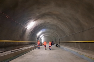
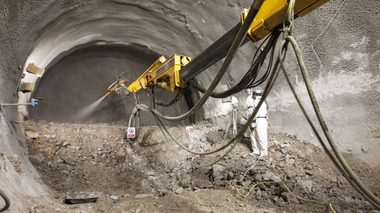
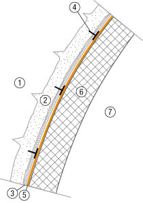
In ITA publications [7] and in [8], the topic of integrating the first sprayed concrete layer into the final lining is frequently addressed. Moreover, new design concepts and construction variants with a permanent sprayed concrete layer have already been successfully implemented in projects. Figure 3 shows a tunnel from Switzerland, Tunnel de Leb, which was completed in spring 2021. Two layers of permanent sprayed concrete were used (280 mm initial support, 150 mm sprayed inner lining), polypropylene (PP) fibres as reinforcement and a sprayed membrane for sealing. This design variant minimised concrete consumption reduced the associated CO2 emissions and also saved time and costs.
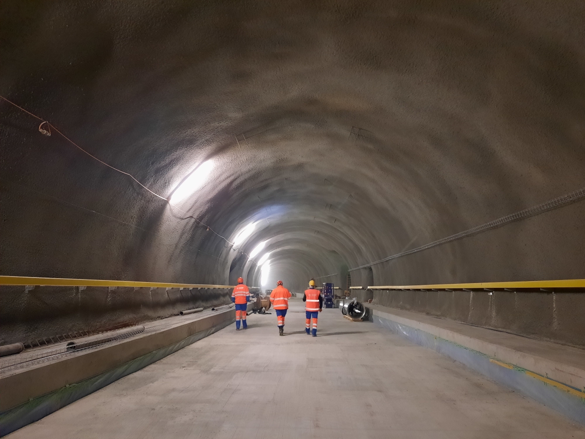 3 | Tunnel de Leb (Switzerland, 2021): Sprayed concrete as permanent lining
Credit/Quelle: Master Builders Solutions
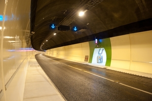
An example from England shows another innovative design approach, combining durable sprayed concrete with steel fibres, a sprayed waterproofing membrane and in-situ concrete for parts of the inner lining. In-situ concrete was chosen to ensure smooth, highly reflective and easy-to-clean wall surfaces (see Fig. 4).
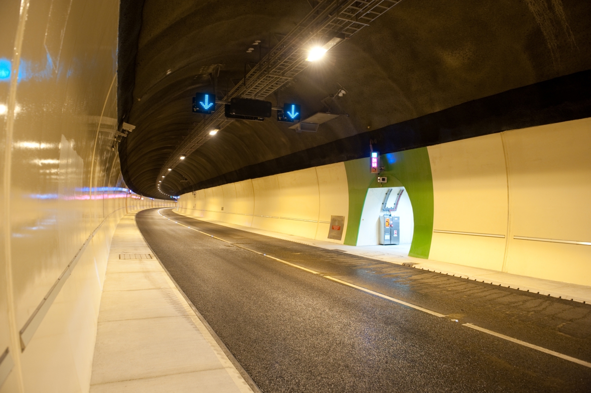 4 | Hindhead Tunnel (England, 2009): Sprayed concrete and in-situ concrete as permanent lining
Credit/Quelle: Master Builders Solutions
Unfounded Concerns Due to
Lack of Standards
However, these design variants continue to be the exception in underground construction. This is closely related to the lack of knowledge and standards as well as the general uncertainty of the planners. However, with the significant developments around the quality of building materials and execution with trained personnel, as previously outlined, the reservations regarding stability and durability are unfounded in most cases.
Aesthetic demands and the intended use of the tunnel should govern whether sprayed concrete is used as the final lining or not, since the rippled surface of sprayed concrete is not suitable for every application. However, in many parts of the underground labyrinth of an infrastructure project, surface requirements are negligible, and a sprayed concrete lining should be considered. This applies, in particular, to tunnel sections such as cross passages, escape routes, ventilation caverns and the like.
If the CO2 balance of a linear metre of tunnel constructed with permanent sprayed concrete is analysed, a significant improvement can be observed compared to a traditional double-shell lining of temporary sprayed concrete (which is not considered permanent) with a permanent inner shell. This is due to reduced concrete volumes placed, as shown in the example calculation in the next chapter.
4 Life Cycle Assessment of Tunnel Structures Using Sprayed Concrete Construction Methods (NATM)
In the following section, various possibilities for reducing the CO2 emissions of a tunnel built using the sprayed concrete method are presented, with calculations. A hypothetical tunnel cross-section with an internal diameter of 10 m in average geology is considered. The tunnel is planned with a round length of 1.3 m, 15 kg/m lattice arches, a 25 cm-thick sprayed concrete lining (C25/30) reinforced with two layers of AQ70 and a 40 cm-thick unreinforced inner lining (C25/30). In this comparison, the influence of other supporting materials was neglected, as they only contribute a minor amount of CO2 (Fig. 1). The concrete for other structural elements is taken into account in a simplified way through the concrete of the circular cross-section.
Comparison of the Planned and the Actually Used Concrete Volumes
Due to practical construction issues and geological boundary conditions, actual concrete consumption is usually significantly higher than the theoretical design dictates. In the following example, a typical excess thickness of 15 cm is assumed for both the sprayed concrete and the inner shell. An additional 10% is added for the sprayed concrete rebound and any residual quantities.
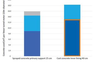
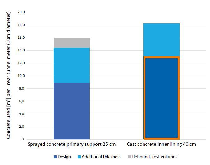 5 | Concrete volume per linear metre of tunnel, target/actual comparison. The lining considered as permanent is marked
Credit/Quelle: Master Builders Solutions/Aldrian
Figure 5 shows the concrete quantities used per linear metre of the model tunnel structure. Taking into account the explanations in Chapter 3, we can assume that of approx. 33 m³ of installed concrete, only about 13 m³ of the inner shell (outlined in orange) are considered to be permanent. For a typical double-shell lining, only 40% of the installed concrete volume (the volume of the inner shell as a proportion of the total concrete volume, less rebound) and the associated CO2 emissions are considered for the design of the static load-bearing capacity of the tunnel structure
CO2 Footprint of a Tunnel With
Double-Shell Lining
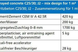
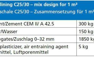
The impact of oversizing on the carbon footprint of the structure is determined below. The calculations are based on typical concrete mixes for the German-speaking region (see Table 1 + 2).
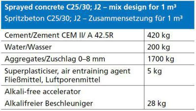 Table 1 | Sprayed concrete mix design
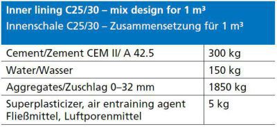 Table 2 | Mix design inner lining
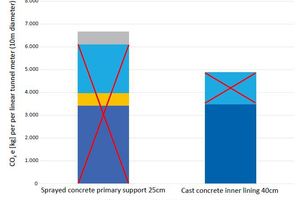
The additional concrete volume requirements described above mean that 4 tonnes of CO2 per metre of tunnel (planned sprayed concrete incl. reinforcement) becomes 6.7 tonnes of CO2 in the course of the lining work (4 tonnes
planned plus surplus thickness, rebound and residual quantities), see Fig. 6.
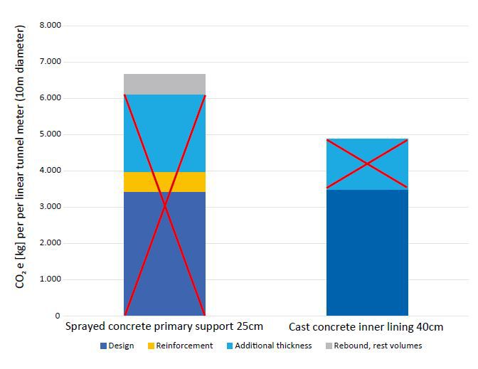 6 | CO2e footprint in kg of concrete used per linear metre of tunnel. Lining considered as temporary (not permanent) is crossed out (calculated with OneClick LCA)
Credit/Quelle: Master Builders Solutions/Aldrian
The sprayed concrete lining, which is considered temporary, makes a significant contribution to the life cycle assessment of the tunnel construction project, yet is often neglected in the design with respect to its load-bearing capacity. If the excess thickness of the inner shell is added to the concrete quantities of the sprayed concrete that are not considered structurally, the result in this example is an enormously high “structurally ineffective” amount of CO2 per linear metre of tunnel.
To illustrate the consequences for the environment, the CO2 contributions of the structurally disregarded components and materials are crossed out in Figure 6 – they account for 68% of the total emissions. Conversely, this means that only 32% of the CO2 emissions caused by the concrete are necessary for the permanent lining. This should be interpreted as a clear instruction to owners and planners to act.
CO2 Savings Potential by
Optimising the Concrete Mix
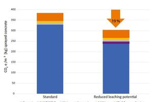
CO2 savings can additionally be achieved through adjusting the concrete mix design. However, requirements for such optimised concretes should be contractually specified during the planning stage, which also promotes competition and innovation in the industry. In the following example, two typical sprayed concrete mixes from Austria are compared: a standard mix (Table 1) with 420 kg CEMII/A per m³ concrete and a modern mix with reduced sintering potential (which reduces leaching from the concrete due to water ingress during the operating phase of the structure and thus reduces the cleaning effort required for tunnel drainage systems), containing 280 kg cement (CEM I 52.5) and 140 kg AHWZ (Austrian speciality of supplementary cementing materials, SCM) according to ÖNORM B 3309. The remaining concrete components are identical and can be found in Table 1. Austrian AHWZ, with a prescribed reactivity and a typical composition of 2/3 granulated blast furnace slag and 1/3 limestone powder, results in greenhouse gas emissions of only 70 kg CO2e/t and is therefore ideally suited to reduce the CO2 footprint of sprayed concrete.
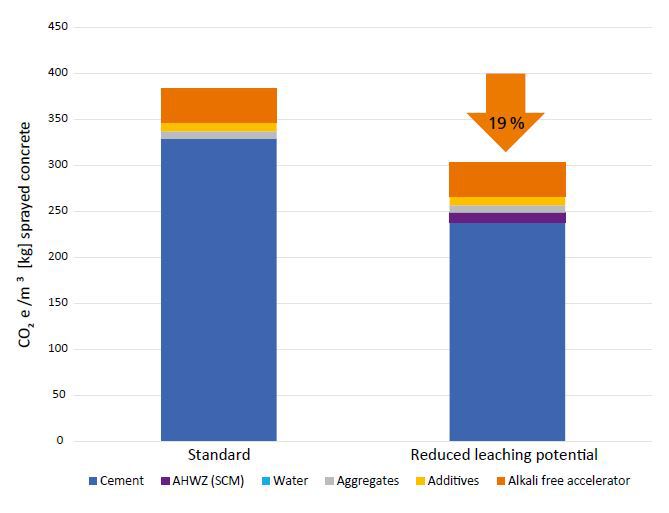 7 | Comparison of the CO2e emissions of two recipes in kg per m³ sprayed concrete (calculated with OneClick LCA; SCM = supplementary cementitious materials)
Credit/Quelle: Master Builders Solutions/Aldrian
The massive reduction in clinker-content and cement volumes leads to a 19 percent CO2 reduction per m³ (see the comparison in Fig. 7). The sprayed concrete mix with its high proportion of SCM to reduce the leaching potential of the sprayed concrete, also offers an additional advantage by reducing the potential need to clean the tunnel drainage system, in addition to its improved life cycle assessment.
Highly optimised sprayed concrete mixes require more accuracy to achieve reliable performance. Ensuring a consistently high cement quality, with the lowest possible fluctuations and strict quality assurance in the production of the recipe, is vital for success. The use of CO2-reduced sprayed concrete on a large scale has been shown to be possible by practice in Austria, where the “280 kg cement +140 kg AHWZ” mix design has almost completely replaced the 420 kg cement mixes that were previously common.
5 Conclusion and Outlook
Sprayed concrete is the support material of choice. It would therefore never be an option to remove it completely in order to reduce the carbon footprint. However, considering the measures described in Chapter 3, there are several ways to optimise the quantity of concrete
required in the cross-section using innovative design approaches, without compromising the structural requirements:
Declare all or part of the sprayed concrete as a permanent lining and include it in the structural design.
Use a sprayed inner shell if this is geotechnically, aesthetically and operationally possible and if a minimum thickness of conventionally constructed inner shell is only required for structural reasons.
Connect the inner and outer shells if considered feasible und useful (single-shell or also as a composite shell with a double bonded sprayed membrane).
CO2 Emissions in Tunnel Construction Projects: Potential Reduction of 10–30%
for Concrete Alone
The above design variants should be assessed in the planning phase, which can significantly reduce the CO2 footprint of a tunnel structure built using sprayed concrete. In each case, it is necessary to check how much excess thickness and higher concrete strength can be factored into static loading calculations and to what extent an additional inner lining is required. Depending on the static loading assumptions and the concrete mix designs used, a potential reduction of between 10 and 30% in greenhouse gases is considered realistic in the literature [7, 9].
As in the construction of buildings, it can be assumed that social and political pressure to adopt more environmentally conscious approaches in underground construction will increase significantly.
The course for more sustainable construction methods must be set as early as possible to maximise the effect. Therefore, clients and planners have a growing responsibility to consider alternative design and construction options as well as high-quality, durable and CO2-optimised construction materials.
Concerning sustainability, a comparison between conventional methods and ecologically optimised variants should be conducted for every project – even if economic aspects and constraints due to standards suggest otherwise at first. In the future, modern performance approaches must be taken into account when it comes to CO2-intensive structural design. This way, ecologically optimised concretes with cement contents below the traditional minimum cement ratio can be used reliably.
Sustainability aspects can only be realised throughout the entire life cycle if the right decisions are worked out and defined in the early planning stages. Integral planning, involving and committing all experts and responsible parties, is imperative to the success of a “green” project. It is also advisable to set environmental aspects as a criterion for awarding contracts in order to contractually define and effectively implement the requirements for environmentally friendly construction.

