Lungern Bypass: Sprayed Concrete Application directly onto Polymer Waterproofing Membranes
In the tunnel widenings for the Lungern bypass sprayed concrete was applied directly onto the flexible polymer waterproofing-membrane (PWM) in the arch area instead of inner lining concrete. The following article shows the experiences by doing this.
1 Overview
In the tunnel widenings for the Lungern bypass/CH, sprayed concrete was applied directly onto the flexible polymer waterproofing-membrane (PWM) in the arch area instead of inner lining concrete. This new approach avoided costly special formwork. The amount of rebound was considerably reduced by first installing a fine steel mesh. The whole job from the primary sprayed concrete sealing, through installation of the waterproofing to the inner poured or sprayed concrete linings demanded great expertise from all those involved.
2 Introduction
The A8 motorway links central Switzerland (Lucerne area) with the Bernese Oberland (region of Thun). The completion of this link is intended to protect traffic from natural hazards (e.g. rock falls), shorten journey times and relieve traffic pressure on the villages along the road. Part of this section is the Lungern bypass, a 4.25 km long structure which will move traffic into and through the mountain. The tunnel itself is 3.57 km long and will take two-way traffic. Linked to the main tunnel is parallel a safety tunnel. In the main tunnel are also 4 service bays, and at the southern end of the tunnel a widening has been designed and prepared for a later connection to the Brünig summit tunnel. The bypass is scheduled to open in 2012.
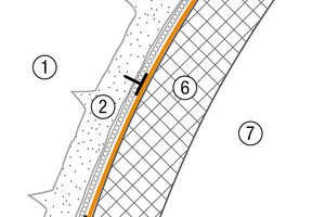
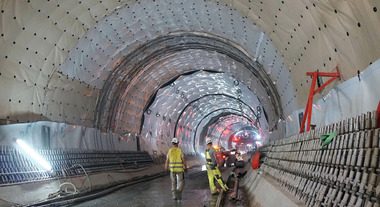
Following drill and blast excavation, the double-layer lining was formed by sprayed concrete support and a load-bearing inner shell. The tunnel is sealed against water ingress by polymer waterproofing membranes. The design life for the waterproofing system and the concrete lining is 80 to 100 years (Fig. 1).
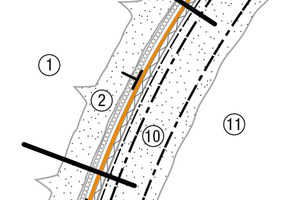
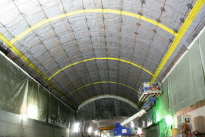
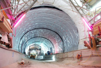
In the 4 service bays, the bore for later connection to the summit tunnel and the cross cuts to the safety tunnel, the arch was not lined with concrete as in the standard profile, but was formed with sprayed concrete. However, in the whole tunnel the walls are made of poured concrete. On the one hand, this gives a considerable cost saving due to avoiding costly special formwork, but on the other hand, great expertise is required from the contractor to do the job professionally. This is because all of the penetrations must be formed and sealed and at the same time suitable precautions must be taken to minimise the potentially high rebound. Accordingly [1], the arch lining is not reinforced in the standard design profile, but the arch had to be reinforced in the service bays (Fig. 2).
3 System structure
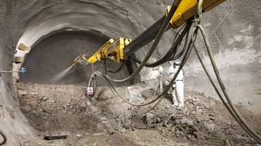
Following excavation the face area was supported with sprayed concrete and additionally this was consolidated in the top heading area by 5 m long friction bolts. Further lining of the excavation stabilisation was then carried out in the heading area with 2 layers of steel mesh reinforcement and sprayed concrete. Finally, 3 cm of sprayed concrete was applied to form the sealing carrier layer for the membrane waterproofing system [1, 2].
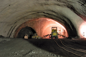
The sealing carrier layer is a necessary component of the waterproofing system. To achieve a reliable and durable seal, it has to meet high demands. It has to level the rough and uneven substrate surfaces in order to enable the waterproofing membranes to be laid without creases and tight to the substrate. The aim is low-stress installation of the polymer waterproofing membrane. For quality control, standards specify the minimum radius of the filleting, permissible unevenness and maximum particle (aggregate) size. The aggregates used must be double crushed chippings and the surface must be free from protrusions. Otherwise the areas must be over-sprayed again to a minimum depth of 30 mm [3, 4] (Fig. 3).
The requirements for the sprayed concrete to form a sealing carrier layer for this project according to SN 564 272 [3] and the specifications were [1]:
1. No steel fibres on the surface [3]
2. Minimum radius 0.2 m [3]
3. Boss spacing to depth ratio ≥ 10:1 [3, 1]
4. Sprayed concrete layer thickness ≥ 50 mm according to [3], but an average thickness of 30 mm being specified in [1]
5. Surface roughness 0 to 8 mm [1]
6. Sprayed concrete class SC 2 [1]
The sprayed concrete for the excavation stabilisation can change the mountain water so that sintering occurs. Therefore an adequate size of drainage cross-section has to be designed and cement-based drainage layers must be avoided. Only a fully functional drainage system can guarantee that water pressure does not impact on the structure [3].
The Sikaplan W Tundrain, type A was used, which is an efficient drainage membrane for tunnels and other underground structures. The mesh is 5 mm thick and is made of foamed polyethylene. It drains the mountain water under no pressure between the sealing carrier layer and the waterproofing membrane, into the tunnel drainage system. This drainage membrane is easy to install and adapts easily to the substrate. It also acts as protection for the polymer waterproofing membrane against damage from the substrate. Sikaplan W Tundrain is spot fixed to the sealing carrier layer with steel bolts and plastic fixing discs (PVC) [8].
A long service life should always be the aim for underground structures because the cost of their design and construction is high. The objective is also to try to keep maintenance costs low. A major requirement for these conditions to be met, is keeping mountain water away from the structure. In conventionally driven tunnel structures, the polymer waterproofing membranes are positioned between the sprayed concrete excavation stabilisation on the mountain side and the load-bearing concrete inner shell. The water pressure and the chemical composition of the mountain water (usually aggressive to concrete) determine the design of the sealing system.
Two types of waterproofing, a drainage and a water-stopping system [4], are used:
1. The drainage system is a discharge concept. It seals the structure against unpressurised mountain water flowing around the arch. The polymer waterproofing membrane ends in the benched drainage area. The water is collected and discharged by the tunnel drainage and dewatering components [3, 4].
2. The water-stopping system is a displacement concept. The mountain water is not discharged, but kept out, so the structure as a whole is waterproofed [3, 4].
The required dryness in the structure is defined by watertightness classes. The classes for tunnels are ’1’ or ’2’, which means ’completely dry’. Therefore damp patches in the concrete are not permitted on the tunnel lining [3].
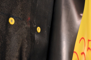
The tunnel construction of the Lungern bypass tunnel is designed to the discharge concept. This means that the system is a loosely laid polymer waterproofing membrane with a layer thickness ≥ 2 mm. The membrane is spot fixed to the sprayed concrete stabilised substrate. According to [5], the minimum number of fixing points per m² is 1 for the invert, 2 for the benches and 3 for the arches. The fasteners are steel bolts with plastic discs at their head. The bolts can be driven into the sealing carrier layer and the waterproofing is then hot air welded to the plastic discs. To enable damage due to installation or subsequent works to be detected and repaired, the membrane must also be coated on the inside of the tunnel with a signal colour [3, 5] (Fig. 4).
The Sikaplan WP 2110-20HL polymer waterproofing membrane used is made from flexible PVC. The homogeneous, self-extinguishing in fire, 2 mm thick sealing membrane has a yellow signal colour to make any damage detectable. This type of membrane can be simply welded to each other by hot air welding system. It is also highly flexible and yet resistant to mechanical stress [7].
Sealing systems are very difficult to repair after the inner lining of the tunnel is completed, because they are no longer accessible. Consequently extreme care is required throughout the installation process from the sealing carrier layer to placing and finishing of the inner concrete shell. Due to these stringent requirements, only qualified specialist contractors with suitable training and references are allowed to carry out this type of installation. The substructure and protective layers must not unduly deform the waterproofing layer and the inner lining must be concreted in such a way that the waterproofing membrane fits tightly on to the structure [3, 4].
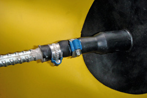
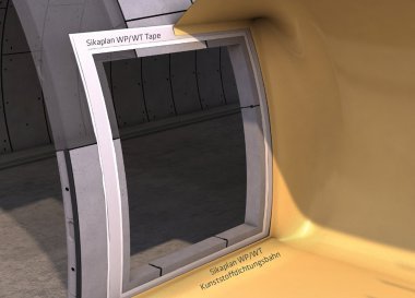
The reinforcement specified in the service bays and the anti-rebound mesh are both fixed to fastening anchors. These are fixed into the substrate with epoxy resin based adhesives and are not installed until after the waterproofing membrane is in position and therefore they represent penetrations. Accordingly [5], they must not reduce the efficiency of the waterproofing and so flanges have to be fitted from the polymer membrane over the anchors and welded to the membrane. The other end of the flange has a watertight connection to the penetrating component by two rustproof clamps and polyurethane-based sealant (Fig. 5) [8].
The protective layers protect the polymer waterproofing membranes from mechanical damage. For waterproofing in underground construction where the concrete inner arch is not reinforced, protective layers are not necessary except around the stopend formwork. But if additional reinforcement is specified, the membrane must always be protected by a protective layer [3, 5].
The Sikaplan WP Protection Sheet 30HE used here is a 3.0 mm thick, homogeneous, PVC based protective polymer sheet with a moulded finish. The sheet is very resistant to external influences and protects the membrane from damage caused by installation of the steel reinforcement, application of the sprayed concrete etc. The protective sheet is spot welded to the waterproofing membrane [7, 8].
As with inner lining concrete, voids can also occur when lining with sprayed concrete. They cannot be compared with the arch gap, but they can be caused if the sprayed concrete on the arch creeps. For this reason measures were taken in the parts of the Lungern tunnel with a sprayed concrete arch to allow for post-grouting after settlement of the sprayed concrete shell. Injectable waterbars were therefore installed directly on the protective membrane. Once injected, these waterbars (Fig. 6) cause closed “compartments” to be produced which are then grouted.
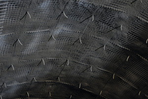
To reduce rebound, close wire meshes are installed on the anchors with a low clearance from the protective membrane. The application is carried out in a grid. The points at the anchors are first secured with sprayed concrete, and then these securing points are joined to form a grid (Fig. 7). This prevents the rebound mesh “flapping” and freshly applied sprayed concrete becoming detached. Finally the compartments formed between the grids can be filled to form a full surface layer of sprayed concrete. At the anchors the first reinforcement layer is then fixed together with a spacer for the second layer, which is fixed in turn to the spacers after overspraying of the first layer. The 2nd reinforcement layer then has to be covered with sprayed concrete and the surface has to be correctly levelled.
The sprayed concrete is applied by the dense-flow wet process using a Sika-PM 500 machine. This double piston concrete pump with an automatic spraying arm has a vertical spaying reach of 17 m. The sprayed concrete had to meet the project specifications and SN 531 198 [6, 1] (Table 1, 2).
4 Other recent projects of this type
• Zurich bypass, Hafnerberg, tunnel bore area, Switzerland, 2002
• Bypass, Vespucio El Salto-Kennedy, Chile, 2000
• Tunnel, Brisbane Australia, 2010
• Rescue tunnel, Fiecht Austria, 2010
5 Conclusions
The replacement of inner lining concrete by sprayed concrete can be seen as a success. The costly special formwork is avoided and the construction quality is comparable with an inner lining of concrete, as other recent projects have also shown (chapter 4). On the Lungern project, it is not yet possible to say if this alternative method has been financially worthwhile. This has to be calculated after the project finishing. However, the figures from the previous projects completed with this method all paint a positive picture.

