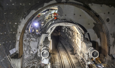
Maroggia Tunnel: Cross-Section Enlargement with a new Method
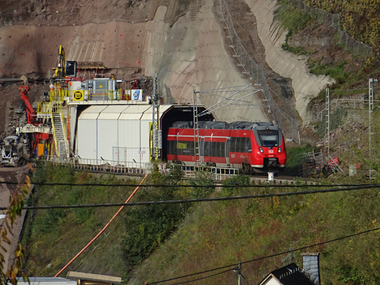
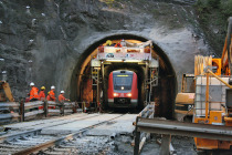
The 570 m long Maroggia Tunnel began operating in 1874. It has now been adapted to the requirements of the “4m Corridor Basle-Chiasso/Ranzo” by being enlarged at one side. The existing masonry was demolished practically to the roof and replaced by an in situ concrete wall, whilst the remaining vault in its structural state was supported almost continuously by a back-anchored reinforced concrete beam installed in advance above the operational track. The work took place under very constricted space conditions, from the construction train with protective wall, so that rail services on the neighbouring track could be maintained. Thanks to the novel construction method, it was possible to reduce construction time to around 1.5 years.
1 Introduction
The Maroggia Tunnel belonging to the Swiss Federal Railways (SBB) is located in the Canton of Ticino on the route between Bellinzona and Chiasso. The twin-track rail tunnel has been operational sice 1874, making it one of the oldest in Switzerland.
In 2011, the tunnel was incorporated in the “4m Corridor Basle–Chiasso/Renzo” (4mK) project, for which a continuous corner height of 4 m for combined rail traffic must be assured for the north-south axis running through Switzerland. A minimum service life of 50 years was demanded for the related maintenance work.
The maintenance project approved and called for by the Federal Office of Transport (FOT/BAV) foresaw the track being lowered by 24 to 25 cm and the cross-section being enlarged at both sides of the vault with new underpinned masonry, partial replacement of the wall using in situ concrete and cutting operations. The objective was to provide the 4mK clearance profile with minimum interference to the tunnel’s bearing structure, which already had been rehabilitated several times.
The high density and close frequency of the SBB projects in Ticino on the north-south axis pose high demands on construction logistics and working cycles. Time frames are narrow and call for a high degree of detail for construction cycles with regard to scheduling as well as consolidation of industrial and operational safety in the twin-track tunnel with single-track services.
In the tender, a contractual variant was included, which opened up the possibility of achieving a substantially shorter construction time so that there was also the opportunity for accomplishing important follow-up projects (upgrading the superstructure). Subsequently this alternative scheme was undertaken with the vault being enlarged only at one side without the invert being lowered. For this purpose, the implementation project had to be completed in the shortest possible time and the construction site closely supervised.
2 Project Description
2.1 Overview
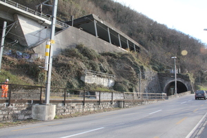
The SBB’s Maroggia Tunnel runs in the immediate proximity of the Lago di Lugano and is flanked towards the lake by the cantonal road and towards the mountains by the A2 motorway. Two motorway tunnels cross above the rail tunnel towards the south, in each case twice at a shallow height (approx. 15 m).
The at least 50 cm thick tunnel lining is horseshoe shaped, both walls and portal zones consist of natural stone masonry (silicic limestone and arkoses), and the crown is lined with mortared full bricks. The brickwork is systematically backfilled with mortared blocks of porphyrite.
2.2 Geology
In geological terms, the Maroggia Tunnel passes through south Alpine volcanic rocks, which belong to the so-called Lugano Volcanic Area. In the tunnel, porphyrites and quartz porphyrites are encountered, which comprise a hard, fine-grained matrix.
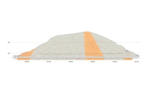
Roughly at the middle of the tunnel (Fig. 1) an open, water-bearing cleft was encountered (source) during tunnelling, in which water influxes of 5–10 l/min are still measured. Roughly 40–50 m to the south of this source, the tunnel passes through a fault dipping approx. 45 ° towards the south. This fault comprises a roughly 30 m thick zone of kakiritised albeit still stable rock.
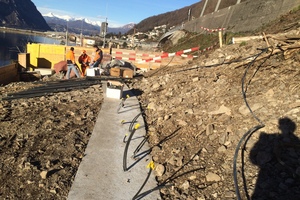
In the north the tunnel finds itself influenced by a landslip, which started moving when the motorway tunnel was built back in 1965/66. At the time a large number of pretensioned anchors were set in the slope (Fig. 2). A part of the rail tunnel suffered deformations. In the course of reconstruction, the tunnel cross-section had to be closed to form a ring by means of invert spreaders.
The Madonna della Cintura Chapel (Fig. 3) built in the 18th century is sited above the south portal. According to the geological prognosis heavily disturbed rock was expected beneath the chapel. However, this was not encountered while executing the enlargement. The portal areas, which were produced by cut-and-cover at the time, are located in a more or less loosely bedded deposit.
2.3 Structural Planning and Construction Process
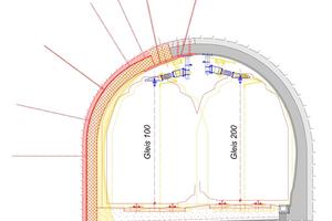
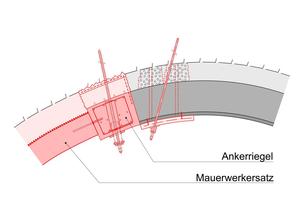
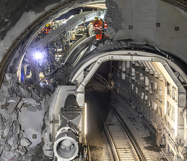
To guarantee the clearance profile, the maintenance project foresaw enlargement of the vault at the track nearer the mountains (G 100) and replacing it by a concrete shell. This embraced removing the existing masonry almost to the roof, whilst the remaining vault was to be supported by a back-anchored reinforced concrete beam, the so-called tie-beam, installed above the operational track in advance (Figs. 4 + 5).
The backfill of the masonry vault was firstly injected with cement suspension to improve the vault’s stability. Furthermore, the masonry was secured with mortar anchors at both sides of the future tie-beam. Reliable information could be gained with regard to the conditions of the profile behind the existing masonry thanks to tensile tests and selected anchor tests undertaken for all the anchors.
The roughly 60 x 80 cm thick tie-beam was produced, reinforced and concreted continuously in advance and subsequent stages. The longitudinal connection was secured by screw-in reinforcements, whereas in the reinforcement cages, empty steel pipes were positioned and concreted in place. The beam was anchored by means of heavy bar anchors (Swiss Gewi 50 mm or self-drilling injection anchors), which were drilled and positioned in the ground through the empty pipes.
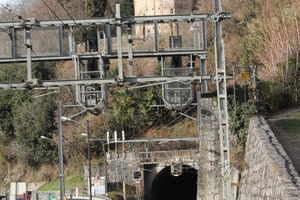
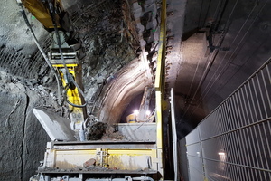
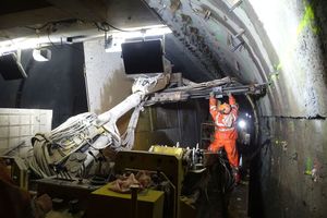
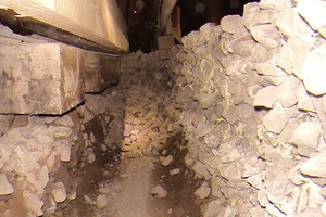
Owing to the constricted space conditions (Fig. 6) the anchors could not be set optimally at an angle from a static point-of-view, something which was compensated for by slightly pretensioning the bar anchors. Evidence for the case of anchor failure could be provided computationally by considering the anchoring of the concrete beam in the ground by the anchor bars. The tie-beam could be installed in such a manner that it was possible to carry out the demolition of the tunnel vault at one side and enlargement over major sections in the rock not only in stages but over the entire length. This enabled more variable logistics and activities to be speeded up. Systematic anchoring was undertaken to support the excavation (Fig. 7) and a shotcrete shell secured by netting was installed.
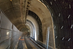
Subsequently, the vault was built stage-by-stage using in situ concrete. The new concrete wall was attached firmly to the tie-beam by means of shear force dowels. In this way, it was possible to secure the transference of force to the remaining masonry vault with minimal deformation, once the anchors relaxed. Drainage matting was installed behind the masonry vault by means of which any water is effectively transferred to the foot of the vault (Fig. 8).
2.4 Unstable Slope
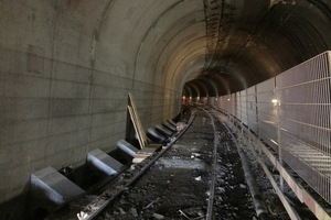
In and around the unstable slope, demolition and reconstruction of the wall was planned stage-by-stage and the initial support was enhanced to avoid reactivating the deformations on the slope. In this area, the tunnel was fitted with invert spreaders set 2.5 m apart after deformations caused by the construction of the road tunnel had occured. During the enlargement procedure, the existing invert spreaders were partially reconstructed and attached to the new concrete wall (Fig. 9).
2.5 Soft Ground Sections
A novel feature on the Basle–Chiasso/Ranzo route related to the one-sided enlargement while train services continued running in the two soft ground sections as well as at the portals. It required some out-of-the-ordinary ancillary measures to tackle this properly. Although consolidation grouting had been carried out within the framework of earlier maintenance measures, the soft ground did not possess sufficient stability without additional measures being resorted to. Furthermore, the shallow overburden did not permit back-anchoring with a concrete beam (tie-beam) as in the rock section.
As a consequence, the concrete beam was installed without anchorage over a short section but with stronger reinforcement so that forces could be more adequately bridged. By and large, the vault enlargement in the soft ground section was constructed in short stages. In order to avoid parts of the masonry becoming detached, the remaining vault was stabilised longitudinally using steel girders and short anchors.
The wall windows to be opened up were secured in advance of the excavation with a dense grid of self-drilling injection anchors and grout (see Fig. 7).
At the south portal the densely bedded soft material was consolidated from the surface with fine cement during an additional grouting campaign. Very heterogeneous material with foreign components is to be found at the north portal, which questioned the efficacy of such injections. The remaining risks affecting stability were minimised through a dense series of “piles” (mortared Swiss Gewi 50 mm, “pile umbrella”) set up at angles to the tunnel (Fig. 10).
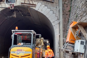
The masonry portal walls also had to be adapted to the enlargement in geometry at one side. The stones of the portal crest were demolished and replaced. The portal wall was secured in advance with the beam using steel girders and horizontal bar anchors fixed in the beam prior to demolishing the final two blocks and the portal crest. The roughwork operations in the tunnel were concluded when the portal crest was rebuilt (Fig. 11).
2.6 Ballast Maintenance
To maintain the ballast during its replaced, a bonding process was introduced owing to the time-related marginal conditions. This is in fact the first-time bonding has been applied in Switzerland on an operational track while maintaining the operating speed (85 km/h). In the process, the client (SBB) took advantage of its research programme from the year 2013 and findings obtained from projects with low-speed restricted sections (30 km/h). Prior to execution, a test field was set up and its status observed over several weeks (Fig. 12). The ballast work was planned with great care so that the amount of time involving open trenches was minimised.
3 Conclusion
The operations in the SBB’s Maroggia Tunnel were brought to a successful conclusion. This objective was achieved thanks to an outstanding performance by all those involved in the project during the final weeks and months. Thus, the twin-track tunnel on the north-south axis, which had been closed at one side since summer 2016, is now completely available for traffic again as from March 2018, following only a little more than a year and a half of construction.
Thanks to the selected, novel construction method featuring an enlargement at one side for the tunnel cross-section, it was possible to cut down on construction time. The unfavourable geological conditions, such as e.g. the soft ground sections beneath shallow overburden, the narrow marginal conditions affecting scheduling as well as the high demands posed on safety owing to ongoing train services on the second track in the tunnel placed great challenges on planning and execution.
Work was undertaken under very constricted space conditions, from the construction train with protective wall, in order to be able to maintain train services on the neighbouring operational track. In addition, the tunnel is located within an unstable slope at the Bissone/Maroggia bottleneck, with the railway line resp. the tunnel running between the cantonal road and the motorway.
Thanks to thorough planning and active, target-oriented collaboration between the companies involved, the project author and the SBB, it was possible to hurdle looming challenges. In spite of immense pressure faced by all those involved in the project, safety was accorded priority.

