Tunnelling Market in Finland
The following article from the organizing Finnish Tunnelling Association welcomes the participants at the ITA-AITES World Tunnel Congress 2011 in Helsinki. It gives an overview over the most interesting tunnelling projects in Finland.
The history of rock engineering dates back some 6,000 years. It has since progressed in a number of waves, the first of which was prehistoric Man’s search for shelter from the elements and refuge from wild animals in underground caves and caverns. Mines, fortresses, fortified palaces, temples and churches were all built into the bedrock - some as monoliths hewn from a single stone.
During the Industrial Revolution of the nineteenth century, society discovered the benefits of underground construction in connection with urbanisation. This led to the second wave of rock engineering, when underground caverns and tunnels were built to improve the community infrastructure, i.e. to serve as sewers, metro tunnels and municipal engineering facilities. Military defence structures and power plant technology were also essentially developed.
The third wave of rock engineering involved the relocation of some human activities from the surface to underground caverns. Sports halls, swimming pools, ice hockey rinks, and permanent art exhibitions exemplify the range of the recreational and cultural applications then undertaken. The business community also brought underground pedestrian precincts, parking and other facilities to city centres.
Environmental problems coupled with a growing awareness of them have provided the impetus for the fourth wave. The minimisation of environment impacts, nature conservation, the desire to protect old urban environments from redevelopment, and stricter legislation have all played their part in stimulating a revival in underground construction.
The waves of rock engineering follow and complement one another. Infrastructural underground facilities such as metro systems and various engineering tunnels and caverns have not lost their relevance in larger cities. Similarly, the third wave of relocating recreational and cultural facilities is also continuing. Now, inspired by concern for the natural and urban environment, the fourth wave is bringing the experience of the rock engineering field to the fore as a timely alternative to traditional surface construction [1].
1 West Metro extension
The west metro will be an extension of the existing Helsinki metro line to the city of Espoo. This fully automated line is estimated to be opened for traffic at the end of year 2015. It will transport more than 100,000 passengers per day [2].
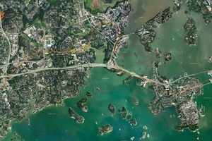
The automated metro traffic will go in 2 parallel, 13.9 km long rock tunnels (Fig.1). As total, 8 stations will be built in rock. 15 vertical shafts with emergency exits are designed to serve technical needs as well. The 2 metro tunnels will be connected at intervals of 100 to 150 m with crosscuts for pressure equalisation, emergency connections, and maintenance work. Nine access tunnels will be made for construction and maintenance. The stations will be approx. 200 m long rock halls with a span of 23 to 25 m. The project requires the removal of around 1.6 million solid m3 of rock. The tunnels and stations will be excavated with the drill-and-blast method and reinforced with rock bolts and shotcrete.
The facilities will be located in the hard bedrock composed of Precambrian granite and various kinds of gneisses. These contain zones with fractured rock, especially undersea and in the areas prone to settling, which from tunnelling point of view will be challenging.
The engineering geology of the area is studied for many years in several stages. The whole design process was started with the old survey data handed over to designers, and new, more concise surveys programmed in areas with wide tunnel spans or critical geological conditions.
The decision to begin construction at the end of year 2008 set in motion an intensive implementation planning with design of the rock structures as one of the central tasks. A large amount of geological data was needed to ensure the detailed plans for the rock structures. The main part of the surveys was therefore mainly concentrated on rock quality investigations. The rock engineering design was mainly focused on project realisation both in terms of time planning as well as of cost planning.
All stations and track switching halls were set to be modelled with 3-D rock mechanical analysis tools to simulate the behaviour of the rock material and to quantify the final amount of reinforcement needed. All tunnel parts and shafts with a challenging design or poor rock quality are also modelled in at least 2-D. The results from the rock mechanical simulations are used, too, to guide building projects in the vicinity of the metro line.
In Keilaniemi, four 100 m tall tower buildings are planned next to and above the metro line and station. The foundation pressure of the buildings is between 2 and 4 MPa for each. In these conditions, it is vital to simulate the interaction between the tunnels and the surrounding structures in advance, so that the critical parts of the construction can be identified and the design can then be optimised accordingly. It has to be confirmed that the additional foundation loads on the surface will not damage the tunnels and, on the other hand, that the tunnels will not cause unacceptable displacements on the foundations of the structures above. 3-D modelling is therefore required to reach the precision required, when working with such variable shapes and load distributions.
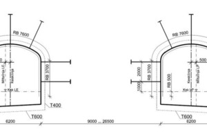
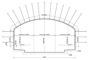
The excavation design is bonded to a beforehand chosen standard profile (Fig. 2, 3). The dimensions for the track tunnel are, on the other hand, based on space requirements of the metro train and its rail system plus an additional 1200 mm for an emergency exit lane. In the parts where the tunnels cross the sea, free space to build a water-pressure-proofed construction is reserved in the excavation profile. Furthermore, a large amount of grouting and reinforcement profiles for a wide range of different geological conditions are needed in addition to the excavation profiles.
2 Ring Rail Line
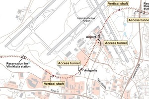
The Ring Rail Line is an important circular rail route of the Helsinki Metropolitan Area. It is an urban two-track passenger line for local traffic in Vantaa between Vantaankoski and Tikkurila and a rail link from Helsinki to Helsinki-Vantaa airport (Fig. 4). The total length of the new line is 18 km, of which 8 km run in twin tunnels mainly under the Helsinki-Vantaa airport area. New SM5 low-floor trains will operate on the Ring rail Line at 10-minute intervals in both directions during peak periods. The maximum train speed will be 120 km/h. Construction of the Ring Rail Line began in spring 2009 by tunnel excavations using drill and blast method. The line will be open for traffic in the middle of 2014 [3].
Computational simulations have been in key roles from the beginning when designing a giant multidimensional rail tunnel system of Ring Rail Line. The tunnel system consists of 4 underground rail stations with access tunnels, pressure equalization and smoke removal shafts, vertical exit shafts, connection tunnels at 200 m intervals, rail exchange areas and heat transfer tunnels in portal areas.
Rock mechanical analysis is needed to predict structural behaviour of rock mass and to determine right location and position and needed reinforcement procedures of underground facility. In Ring Rail Line all 4 underground stations are simulated using interpreted geometrical and mechanical model of rock mass. Rock mechanical simulations showed the critical areas which need extra reinforcement procedures and stability supervision during construction. Rock mechanical analysis are done using 3DEC-program and critical key blocks are analysed using Unwedge-program.
The aerodynamic simulations were carried out in 2 steps. The complete tunnel system was simulated using 1-dimensional transient fluid dynamics code IDA Tunnel. The code solves the aerodynamic flows occurring in the tunnel network due train motion and thermal or external influences governing incompressible fluid flow equations in 1-D. The 3-dimensional effects of the flow are modelled using pressure loss coefficients and friction factors as in normal practise for transient 1-dimensional pipe flow networks. Different tunnel system layouts and changed tunnel profiles have been investigated in 1-D with various train timetables to determine the peak air speeds in platform areas and in escalator shafts of the underground stations and evaluate the maximum pressure loads against tunnel doors and glass structures in the stations.
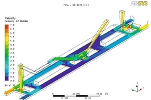
The station with the highest identified air speeds in the escalator shafts was simulated in 3-D to account for the 3-dimensional flow effects and highlight the areas with the highest velocities. The air flows from/to the adjacent tunnel sections obtained from 1-dimensional simulations were used as boundary conditions for the 3-D studies. The 3-D simulations were carried out using the commercial CFD software package ANSYS CFX. Simulations in the early phase showed that the highest air speeds are found at Ruskeasanta station (Fig. 5) and therefore it was chosen to be modelled in 3-D. As well as highest observed speeds in escalator shafts, Ruskeasanta station has the disadvantageous situation of 2 escalator shafts which differ in length by a factor of 2. The pressure drop caused by a shorter escalator shaft is much smaller than the one caused by the longer shaft. The differences in the air velocities are substantial.
In Ring Rail Line the train schedule was noticed to have a significant influence to air flows and pressures in escalator shafts and access tunnels. Air speeds can reach up to 7.5 m/s for very short periods. The maximum speeds are found at the start of the daily service when trains enter the tunnel system. During regular operation the peak air speeds are approx. 6.0 m/s. The simulations show that the maximum air speeds are localised and only occur a very limited time. As regulations allow the air speeds to increase to a maximum of 10 m/s in rare cases, the present design of the tunnel system is assessed to be acceptable.
The fire scenarios are dimensioned by operating train and modelled using the geometry of the complete tunnel system. Two different fire scenarios were simulated with 1-dimensional software IDA Tunnel to generate boundary conditions for detailed 3-dimensional analysis. The worst case fire location in the tunnel section with highest slope between Viinikkala and Aviapolis station was chosen to be simulated.
The 1-dimensional simulations show that ventilation system is capable to produce air speed of approx. 3.5 m/s in the tunnel section in question. This velocity is higher than the critical value to prevent smoke back-layering for the corresponding fire power of 40 MW.
The 3-dimensional Computational Fluid Dynamics (CFD) simulations show that the smoke propagation in the first minutes after the start of fire is guided by the initial air movement. Depending on the fire location the turbulence of the air flowing around the train can destroy the natural stratification of the hot smoke and cause a decreased visibility in the complete tunnel cross-section.
In both scenarios the temperatures in a rail tunnel along the path towards the fire location will be less than 70 °C at all times. As soon as the ventilation system is running at full power, all the smoke produced by the fire will be pushed towards the smoke removal shafts.
The smoke propagation and evacuation simulation of Ring Rail Line were done with Fire Dynamics Simulator (FDS) and FDS-Evac software. The evacuation simulation presents how much time passengers need to exit tunnels or stations to the safe side. According to exit simulation the interval of cross connecting tunnels between rail tunnels was designed to be 200 m. The passengers of the whole train are simulated to exit through connection tunnels to the safe side in 6 minutes in a tunnel sections. The simulation showed in the stations that escalator shafts and upper levels of the station should be fire-compartmented from the platform level to allow exit to the safe side.
3 Spent nuclear fuel storage
The Finnish nuclear power plants have been in operation for more than 25 years. Two BWR units are operated at Olkiluoto (2 x 860 MWe) by Teollisuuden Voima Oy (TVO), and 2 PWR units at Loviisa (2 x 488 MWe) by Fortum Power and Heat Oy (Fortum). One PWR unit (1600 MWe) is under construction at Olkiluoto [4].
According to the Nuclear Energy Act, all nuclear waste generated in Finland must be handled, stored and permanently disposed of in Finland. The 2 nuclear power companies, TVO and Fortum, are responsible for the safe management of the waste and for all associated expenses. TVO and Fortum established a joint company, Posiva Oy, in 1995 to implement the disposal program for spent fuel.
Preparations for nuclear waste management were commenced in Finland already in the 1970’s when the power plants were still under construction. In 1983, the Government confirmed a target schedule for spent fuel management, in which the construction of the final disposal facility was scheduled for the 2010’s and the start of final disposal for 2020.
Potential sites for the disposal of spent fuel were screened already in the 1980’s, followed by detailed site investigations in the 1990’s and an environmental impact assessment in late 1990’s. In 1999, Posiva submitted an application for a Decision-in-Principle (DiP) to choose Olkiluoto as the site of the final disposal facility. The Government issued a DiP in favour of the project in December 2000, and the Parliament ratified the decision in May 2001.
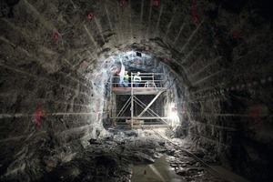
Investigations, characterization and more detailed design could now be focused into one site. A decision was made to excavate an underground rock characterisation facility, ONKALO, at Olkiluoto. The ONKALO facility shall be constructed in such a manner that it allows further characterisation and research work (Fig. 6) to be carried out without jeopardising the longterm safety of the repository site. In addition, it should be possible later to link the ONKALO to the repository so that they are integrated. Excavation work for ONKALO began in September 2004.
Olkiluoto site has ready infrastructure built for the nuclear power plants. One reactor is also under construction. For the design of above ground facilities this meant that several buildings and systems exist already and these are not needed to construct. For underground disposal facility this meant that the connections to above ground must fit in existing infrastructure, roads, power lines etc.
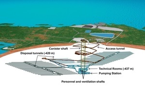
Outline design of the Disposal Facility was developed during 2008 to 2009 and published in 2010. The disposal facility consists of surface connections, technical rooms at an approx. level of -437 m, the central tunnel network and the repository facilities at an approx. level of -420 m. The deposition tunnels and deposition holes drilled in their floors are collectively called the repository. The spent nuclear fuel is deposited in the repository. Connections to the ground level from the disposal facility are via the access tunnel running at a slope of 1:10, and via 5 vertical shafts. Shafts are a canister shaft, a personnel shaft, an inlet air shaft and 2 exhaust air shafts. A layout example of the disposal facility is shown in Fig. 7.
An underground rock characterization facility, ONKALO, is excavated at the disposal level. ONKALO has been designed so that it can later serve as part of the repository. The first part of the disposal facility will be excavated after the construction licence phase in the 2010s, and operations will start in 2020. The fuel from 4 operating reactors as well the fuel from the fifth nuclear power plant under construction has been taken into account in designing the disposal facility. The amount of spent nuclear fuel is 5550 tU. The disposal facility is excavated and closed in stages over the long operational time of about 100 years.
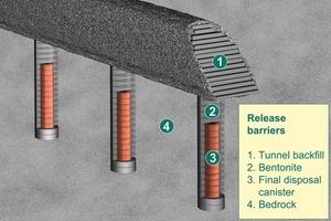
The disposal canisters are deposited in holes drilled in the deposition tunnel floors. The holes have a diameter of 1.750 mm, and their depth is 7.80 m for OL1-2 canisters, 8.25 m for OL3 canisters and 6.60 m for LO1-2 canisters (Fig. 8).
When the deposition tunnels are located at distances of 25 m from each other, the minimum distance between deposition holes is 9.0 m for OL1-2 canisters, 7.2 m for LO1-2 canisters and 10.6 m for OL3 canisters. The maximum length of deposition tunnels is limited to 350 m for reasons related to ventilation technology and occupational safety.
A total of 2820 disposal canisters will be required for this quantity. In an optimal situation where all deposition tunnels are 350 m long, and the distance between deposition holes is always equal to the specified minimum distance, a total of 80 tunnels will be required. The total length of all deposition tunnels would then be about 28 km. In practice, the total number and total length of deposition tunnels will be greater than that. Due to reasons related to the bedrock, all deposition tunnels cannot be of the maximum length, nor can the distance between deposition holes always comply with the specified minimum distance. The total volume of the disposal facility is approx. 1.1 million m3. The maximum open volume is around 0.6 million m3, because the disposal facility is excavated and backfilled in stages.
The disposal facility is divided into a controlled area and an uncontrolled area. Canisters are always handled and lowered to the deposition hole in the controlled area. The excavation and construction of new tunnels and the backfilling of the tunnels is carried out in the uncontrolled area. Extensive material transfers, such as transfers of excavated rock and backfill materials, are done in the access tunnel. Separate ventilation systems are provided for the controlled and the uncontrolled area.
When all the canisters have been disposed of in the deposition holes and operating and decommissioning waste from the encapsulation plant has been disposed of, the closure phase of the repository will begin. The structures and the systems of the repository are first removed so that no harmful amount of materials is left in the repository. After that the rooms are backfilled and sealed with closure structures.
4 Conclusions
Underground construction is an essential part of modern and responsible environment construction. It can be applied grobally to help solve the problems involved in developing and improving communities. Rock construction literally adds a new dimension to community development [1].

