SBB Dual-Track Tunnel Ligerz: Eliminating a Traffic
Bottleneck With Complex Boundary Conditions
 Credit/Quelle: SBB
 Credit/Quelle: GILIG (Gähler und Partner AG)
 Credit/Quelle: GILIG (Gruner AG)
 Credit/Quelle: GILIG (Gruner AG)
 Credit/Quelle: GILIG (Gruner AG)
 Credit/Quelle: MFR Géologie-Géotechnique SA
 Credit/Quelle: GILIG (Gruner AG)
 Credit/Quelle: GILIG (Gähler und Partner AG)
 Credit/Quelle: GILIG (Gähler und Partner AG)
 Credit/Quelle: GILIG (Gähler und Partner AG)
 Credit/Quelle: GILIG (Gähler und Partner AG)
 Credit/Quelle: GILIG (Gähler und Partner AG)
The Ligerz–Twann dual-track extension project will eliminate the last single-track section on the SBB’s southern ridge-base line. In addition to a dual-track tunnel amidst challenging geological conditions, the project also includes various engineering structures, some of which are extremely demanding. Planning and construction are characterised by limited space and numerous environmental constraints and protected zones.
1 Introduction
The SBB’s southern ridge-base line (Jurasüdfußlinie) runs from Geneva/Lausanne via Neuchâtel and Biel to Basel/Zurich. The cur- rent single-track line in the Ligerz–Twann section is a bottleneck on this important west–east axis for both passenger and freight transport. Expanding to dual tracks will increase the capacity and improve timetable stability [1].
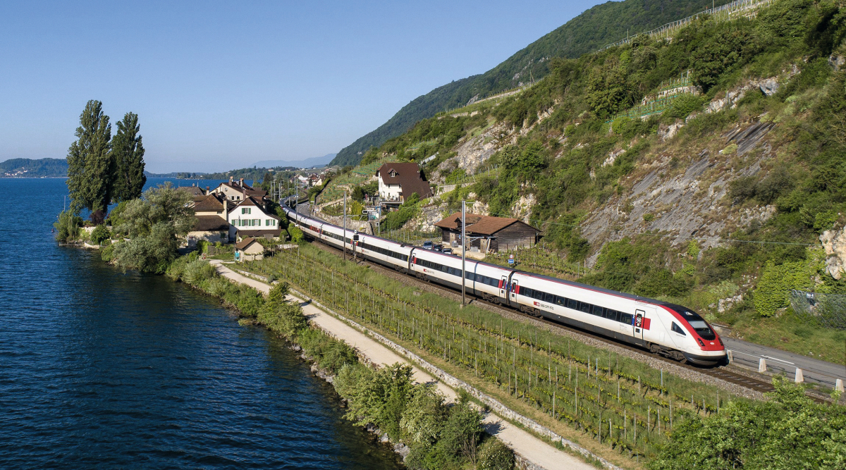
The current route runs along the lakeshore of Lake Biel, right through the villages of Schafis, Ligerz and Bipschal, which makes a dual- track extension in this area impossible (Fig. 1). The railway line will therefore be relocated to a new dual-track tunnel that bypasses the residential area on the mountainside. This will also make life easier for local residents and improve the surrounding landscape.
The Ligerz–Twann dual-track extension project will eliminate the last single-track section on the SBB’s southern ridge-base line. In addition to a dual-track tunnel amidst challenging geological conditions, the project also includes various engineering structures, some of which are extremely demanding. Planning and construction are characterised by limited space and numerous environmental constraints and protected zones.
Planning was significantly influenced by both limited space and numerous protected zones in the area. The region, on Lake Biel’s west shore, is listed in the Federal Inventory of Landscapes and Natural Monuments of National Importance (BLN), individual villages nearby are included in the Federal Inventory of Swiss Sites worthy of Protection (ISOS), certain stretches of road are listed in the Federal Inventory of Historic Transport Routes in Switzerland (IVS) and the archaeological sites of the lake dwelling settlements around the western portal and Twann railway station are part of a UNESCO protection zone. There is also a potable water supply well in the eastern portal area that supplies three municipalities and whose protection zones directly adjoin (S2) or are tangential to the construction perimeter (S3) [2].
2 Project Overview
2.1 Project Structure, Key Objectives
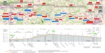
The expansion project covers a length of 4.7 km. This includes 1.3 km for the western track extension, 2.1 km for the dual- track tunnel, 0.5 km for the eastern dual-track extension and 0.8 km for the Twann station renovation work. Numerous larger engineering structures will also be built (Fig. 2).
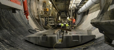
In the western sector, these structures include extending the underground passages Poudeille and La Neuveville, the 114-m-long N5 viaduct (Fig. 3) for the relocation of the N5 motorway half-junction, a combined emergency catchment tank for the railway and motorway tunnels and the Poudeille railway technology building.
In order to create space for the new dual track in the eastern sector, a lake fill must first be constructed. Due to poor geotech- nical conditions in the area – including layers of lacustrine chalk – the route in this area is being constructed on a 228-m-long, pile-founded concrete slab (Fig. 4). Directly at the eastern portal, the cantonal road will cross under the future railway line with a 340-m-long groundwater trough (Fig. 5). An emergency tank and a railway technology building are also being built at the eastern portal. In the Klein–Twann area, the underground passage will be extended and a 149-m-long retaining wall will be built to widen the route.
The Twann station will be completely remodelled and made handicapped accessible – with two side platforms, a new underground passage and new access ramps. The station building will be demolished and a new railway technology building will be constructed under the platform on the lake side of the tracks.
The old railway track between Schafis (western portal) and Bipschal (eastern portal) will be completely dismantled once the new railway line goes into operation. In partnership with SBB, the municipalities have drawn up a development plan for the recultivation and subsequent use of the approximately 31 000 m2 of vacant land. This plan envisages areas for viticulture and public use – including green zones and paths for non-motorised traffic – as well as ecological compensation areas. The project will be realised by the municipalities concerned starting around 2029.
2.2 Geology
The project site is located on the southern slope of the Jura mountain range, which consists of rock from the Triassic to the Tertiary period. Some of these rocks are highly tectonised and form several synclines and anticlines. On the surface, the rocks are covered with moraine and slope debris.
In the western portal area, there are mainly marl formations with rock bedding angles that are unfavourable to the future structure. In the eastern portal area, there is a landslide zone consisting of slope debris and the Goldberg rock formation.
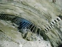
The tunnel will cross the geological formations twice due to its curved geometrical alignment. The Gold- berg rock formation, a heterogeneous alternating layer of limestone, marly limestone, marls/clay marls and dolomite, as well as the upper Twannbach rock formation, are geotechnically problematic. In addition, strong karstification with karst water inflows of up to 2000 litres per second can occur in the limestone layers of this formation. The Goldberg rock formation is tectonised, heavily fractured in places and has local source water potential (Fig. 6).
From a hydrogeological point of view, the Jurassic and Cretaceous strata can be divided into two main categories: Limestone series, which are traversed by fracture zones and karst formations and are therefore potential groundwater carriers, and marl series, which represent groundwater barriers, in which little or no flowing water can be expected. There are two aquifers in the limestone series, which are separated from each other by the Goldberg rock formation. The Brunnmühlen spring, the central element of the regional water supply, is only supplied by the lower aquifer. The inner section of this aquifer can be highly pressurised during floods (pressure of up to 6 bar at tunnel level).
3 Dual-Track Tunnel
3.1 Most Important Construction Elements
3.1.1 Western Preliminary Cut-and-Cover
Tunnel
The western preliminary cut is the first construction step in order to be able to start tunnelling quickly and to install the conveyor belt for transporting the excavated material to the floating loading platform. In the eastern, 24-m-long portal area, the building pit, which will be up to 23 m deep, will be secured in the upper part and at the portal wall with sprayed concrete and soil nails (anchors), and in the lower half with a 10-m-high soldier pile wall and prestressed anchors. In the western area, the 201-m-long cut-and-cover tunnel will be built largely using the top-down construction method with walls made of overlapping bored piles (Ø 1.0 m) (Fig. 7).
As the motorway exit will run over the future location of the cut-and-cover tunnel and has to be temporarily rerouted for construction, the shell will be built in two stages. Due to the sloping terrain in the western section and the restrictions present due to the neighbouring Bielerstraße, the cut-and-cover tunnel will be constructed using a mixed construction method. A temporary pre-stressed bored pile wall will be erected in an open building pit on the mountainside, which will then be connected to a concrete frame construction. The railway technology building to the west will be built directly adjacent to the cut- and-cover tunnel.
3.1.2 Mined Tunnel, Main Heading
The 1865-m-long mined railway tunnel will be excavated by drill and blast in a top heading excavation. Around two thirds of the advance will be uphill and the last 410 m will be downhill. The standard cross- section is designed to include a double-lining structure with a waterproof membrane and drainage with a separation system. A floor invert is planned to be constructed in the geotechnically difficult Goldberg and upper Twannbach rock formations. Depending on the security class, bolts, wire mesh and sprayed concrete or a (closed) steel structure will be installed to prevent collapse. The thickness of the inner lining is 40 cm (Fig. 8).
Heavy karstification with large water ingress is possible in the limestone formations. In the event of an incident, the primary aim is to collect the water, channel it around the tunnel and discharge it back into the mountain. In addition to the technical rooms in the cross-connections, five niches for railway technology equipment and personal protection niches every 50 m will be created in the railway tunnel. With the exception of the western portal area, the carriageway will be equipped with a slab track.
3.1.3 Eastern Preliminary Cut, Portal Structure and Counter Drive
The eastern preliminary cut is located in steeply rising, geotechnically difficult terrain. The upper part of the up to 23-m-deep building pit will be secured with sprayed concrete, soil anchors and prestressed anchors, while the lower part will be secured with a drilled pile wall (Ø 1.0 m, L: max. 27 m), which will, in turn, be secured with prestressed anchors (Rak 2030 kN).
The building pit for the cantonal road undercrossing is located directly adjacent. The undercrossing structure, the base of which lies below the groundwater level, is secured with an overlapping bored pile wall (Ø 1.0 m). The bored piles will also serve as buoyancy protection in the final construction stage.
The 45-m-long portal structure is a solid, rectangular frame structure (ceiling d: 1.40 m, valley-side wall d: 1.40 m), which is based on a pile foundation (Ø 1.0 m, l: up to 35 m) due to the topographical conditions and the unfavourable subsoil properties (Fig. 9). In order to ensure slope stability in the final state of the project, the piles securing the building pit are considered to be statically co-active.
As the Goldberg rock formation is heavily weathered down in this area, a reverse drive will be created from the building pit. This will be carried out as top heading excavation with a pipe umbrella (max. three stages of 10 m each, overlap 5.0 m). The top heading abutments will be reinforced with micropiles.
3.1.4 Cross-Connections
The railway tunnel is designed to have four emergency exits, which lead via cross-connections (CC) to the safety tunnel (SaTu) in the N5 motorway tunnel. Due to the different alignment of the railway and road tunnels, the length of the CCs varies between 42 m and 100 m, as does the height difference from 8.9 m to 13.4 m. Even with a maximum longitudinal gradient of 10%, for two CCs this difference in height can only be overcome with a staircase. A sufficiently large vestibule will be provided to prevent a backlog in front of the stairs in the event of an incident.
In the tunnel-side area of the CC, there will be a technical room at the side for various railway technology equipment. This area, including the technical rooms and stairwells, has a double lining including a waterproof membrane, while the remaining area up to the SaTu has a single lining (Fig. 10).
The excavation will be carried out by drill and blast. The last few metres before the SaTu will be excavated using mechanically assisted tunnelling in rock in order to minimise vibrations.
3.1.5 Relocating the Ventilation Gallery
After around 1 km of excavation, the railway tunnel will pass through another gallery that currently supplies an underground operations centre for the motorway tunnel and a civil protection bunker with fresh air, electricity and drinking water – and through which the wastewater from these facilities is also drained. It is not possible to cross over or under this gallery due to the railway tunnel’s alignment constraints. The gallery therefore has to be relocated for the construction of the railway tunnel. The new gallery will run in a lateral curve over the railway tunnel.
In the crossing area, the base of the new gallery is designed as a solid, reinforced slab. This will also act as roof protection for the railway tunnel. The percolation water entering the tunnel will be fed into the collection pipe in the railway tunnel. Due to the elevated section in the new tunnel, the wastewater must be pumped via a separate line into the existing pipeline. Once the new tunnel section has been commissioned, the old tunnel will be partially backfilled (Fig. 11).
3.2 Structural Challenges
This project presents numerous tunnel construction challenges. In addition to the problems explained in detail below, these challenges include the interaction between the building pit support at the eastern preliminary cut and the pipe umbrella used for the counter drive, the difficulty in accessing the construction site with very limited space, and the challenging geology featuring swelling potential, karst formations and lacustrine chalk.
3.2.1 Starting the Tunnelling Work at the Western Portal
For the first 35 m, the tunnel will have a low cover of 8.0 m to 10.0 m. In this area, marl and limestone formations are traversed, which are overlaid with talus material and scree.
The SaTu operations centre, a storage building and a residential building will be located in the immediate vicinity of the tunnel. The latter building is only 11 m from the future tunnel axis, with an excavation width of 12.8 m, and is classified as settlement-sensitive. In order to minimise vibrations and settlements, top heading excavation will be carried out with mechanically assisted tunnelling in rock.
In order to avoid settlements or deformations of the residential building as much as possible, precautionary measures, such as substantial face anchoring and forepoling every 1 m, are necessary. In addition, a rapid closure of the inner lining is planned, in that after two top heading excavation stages of 1 m each, the benches will be completed and a floor invert installed. The hollow space will be secured with steel beams (HEB 200) and a 30-cm-thick reinforced concrete shell, in the area of influence of the residential building the distance between the steel beams will be reduced.
3.2.2 Excavating the CC and Connecting to the SaTu During Operation
The constructional and operational challenges involved in constructing the CC include the large height difference between the railway tunnel and the SaTu (Fig. 10) and the connection to the SaTu without restricting the operation of the motorway tunnel.
For the safe operation of the motorway tunnel, the functionality of the SaTu (ventilation, escape route) must be guaranteed at all times. For this reason, all structural work on the CC must be carried out from the railway tunnel. The only exception is a bulkhead wall, which will be constructed before excavation in the SaTu. This bulkhead wall will be located outside the SaTu’s escape route profile, will be dustproof and will serve as a temporary support structure when the SaTu’s load-bearing vault lining is locally demolished during the breakthrough of the CC.
The CC will be excavated uphill with a maximum gradient of 10%. The “staircase cavern” at CC 2 and 3 will be excavated from bottom to top. For subsequent tunnelling of the second part of the CC, either a temporary ramp must be constructed or the tunnelling equipment must be raised to the top heading level of the cavern using a lifting device. This height difference must also be overcome for muck transport and supplying the excavation support materials (such as anchors, shotcrete etc.) to the tunnel face.
3.2.3 Relocation of the Ventilation Gallery During Operation
As the ventilation gallery is necessary for the safe operation of the motorway tunnel, the new gallery must be completed before the existing one can be taken out of service. In addition, construction work must be carried out while maintaining the functionality of the ventilation gallery at all times.
For this purpose, a dustproof and airtight bulkhead wall will be erected in advance on the side of the operations centre; a fan with a dust filter will also be installed to supply fresh air. The escape route will be ensured with an airlock, and a temporary footbridge will be built in the future crossing area. The utility ducts will be temporarily relocated.
The railway tunnel’s top heading drive will continue until about 25 m before the ventilation gallery. The drive will then be lowered and the standard cross section reduced. The reduced profile will pass under the existing tunnel. Around 25 m after the crossing, excavation will return to the standard level and be expanded to the standard profile.
The new ventilation gallery can then be constructed by drill and blast via a temporary access point from the railway tunnel. The connections to the existing tunnel will be excavated using a roadheader.
After the new ventilation gallery has been completed and all infrastructure has been put into operation, the temporary access point and the section of the ventilation gallery that is no longer needed will be filled in.
3.2.4 Measures Against Vibrations During Operation
In the western portal area, the future tunnel will be located very close to existing structures. A heavy-duty mass-spring system (MSS) will be installed in this section to prevent negative effects from vibrations and structure-borne noise during operation. Due to the track alignment boundary conditions, the transition from ballast track to slab track cannot take place outside the tunnel – instead, it is only possible from 380 m into the tunnel. The MSS must therefore be combined with a ballast track. A separate concrete trough (= mass) will be constructed for each of the two tracks to accommodate the ballast track. The concrete trough, for its part, will be supported on Sylomer blocks (= spring). This design will decouple the tracks from the tunnel structure and minimise the transmission of vibrations from operations (Fig. 12).
The complexity of this design is significantly increased by additional boundary conditions: The dimensioning of the MSS assumes that the concrete trough is a rigid, continuous beam over the entire length of 344 m. The entire structure is located in an S-shaped track transition curve, which means that the transverse gradient and superelevation, and therefore the height of the trough, are constantly changing. For these two reasons, only partial pre-fabrication is possible. The ballast trough must be drained, whereby the connection to the waste water pipe must be flexible due to its elastic bearing. Because the Sylomer blocks have a shorter service life than the concrete structure, they must be replaceable.
3.3 Materials Management
Around 890 000 tonnes of rock will be excavated during the construction of the tunnel, 88% of which comes from excavation (Table 1). Excavated material that cannot be directly reused within the project is currently being transported to the municipality of Cornaux and recycled there. Depending on the quality of the material, it is either used as raw material for the cement industry or processed as bulk material or aggregate for concrete. The remaining material will be used for recultivation (backfilling of old quarries).
The material management concept stipulates that around two thirds of the excavated material will be transported away by ship. For this purpose, a floating loading platform will be installed in the western portal area. In Cornaux material will be transferred from ship to conveyor belt via an existing transfer station. With this concept, lorry journeys and thus environmental pollution (noise, dust, CO2) can be significantly reduced. It also simplifies transport of the lake fill material. The lake fill material can also be transported by ship from the western portal to the eastern side and dumped there. This will significantly reduce the number of lorries passing through the villages and crossing the tracks.
4 Execution of Construction
To realise this project, the construction work was grouped into three shell lots. The western preliminary lot comprises the track work, including engineering structures, on the western section of open track. These construction works have already been completed. The Twann lot includes reconstructing the Twann railway station (track construction and engineering structures) as well as all enginee- ring structures in the Klein–Twann area. This lot has been under construction since the end of 2022. The majority of the construction work will be completed in June 2024 with the station reopening, with the remaining work planned to be completed in 2029.
In addition to the tunnelling work, the main lot also includes the preliminary cuts, cut-and-cover structures, technical buildings and emergency basins, the relocation of the N5 half-junction and viaduct, the underground passage under the cantonal road (groundwater trough) at the eastern portal and the widening of the eastern track, consisting of lake filling and the pile-founded load distribution slab.
Due to the limited space available, to reduce the number of interfaces and to optimise the overall construction programme, the decision was made to also install some of the railway equipment in the tunnel through the main lot. This includes the carriageway (ballasted track and slab track), the overhead conductor rail, the handrail and the escape route signage, all escape route doors to the CC and the SaTu, as well as the doors to the technical rooms in the CC, and the steel construction and mechanical work in the CC. In addition, the main contractor is also constructing the slab track in the eastern dual carriageway extension area (load distribution slab).
Constructing the main lot was delayed due to submission complaints. Construction started at the beginning of 2024. Tunnelling is scheduled to begin in October 2024, with breakthrough expected to take place in early 2027 (Status March 2024).
Tunnel Ligerz
Project Data/Projektdaten
Client/Bauherr
CFF SA, Infrastructure Ouest
Planning and construction management
Planung und Bauleitung
GILIG: Groupement d’Ingenieurs Ligerz
• Gruner AG, Renens/Basel
• Gähler und Partner AG, Ennetbaden
Construction of the main lot (tunnel)
Bauausführung Hauptlos (Tunnel)
Consortium IBD
• Implenia Suisse SA, Echandens/Glattpark
• F. Bernasconi et Cie SA, Les Geneveys-sur-Coffrane
• De Luca SA, Bienne
Construction time/Bauzeit:
Shell construction/Rohbau 2022–2027,
equipment/Ausrüstung 2027–2029
Construction start, preliminary lot/ Baubeginn Vorlos: 2022
Construction start, main lot/Baubeginn Hauptlos 2024
Commissioning/Inbetriebnahme: 2029
Total investment tunnel/Baukosten Tunnel: CHF 431.9 Mio.
Total length/Gesamtlänge: 2119 m
Excavation cross section/Ausbruchquerschnitt: 110.5 m2 (125.8 m2 with invert/mit Sohlgewölbe)