Jagdberg Tunnel on the A4 Motorway Eisenach–Görlitz
A report on the start of construction on the Jagdberg Tunnel in Thuringia was provided at length in tunnel 1/2009 p. 8 ff. The following article follows on from presenting the project launch and concentrates on excavating the tunnel, the geology and the effects of the
drive that was undertaken.
1 Introduction
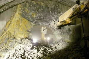
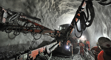
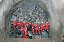
The moment had arrived on August 27, 2009. Practically almost 9 months after work officially began on the tunnel on September 26, 2008, the official breakthrough of the first of the 2 roughly 3,100 m long tunnel bores, the southern bore, was ceremoniously celebrated. A week later on September 3, 2009 the northern bore followed. As a result contrary to all forecasts the crown drives for the southern and northern bores were completed some 9 months earlier than predicted (Fig. 1).
Both bores were driven with a slight time gap by drill+blast with an advancing crown in a continuous operation. The high rates of advance of up to 9 m/working day given a maximum length of advance of 1.50 m in the crown and an excavated cross-section in excess of 100 m²/m for the standard cross-section are by and large attributable to the following:
■ Optimised fleet of machines geared to the geological conditions. Each of the 4 driving points was provided with its own equipment (drilling rig, spraying manipulator, wheel loader, dumper etc.)
■ Independent supply of the various driving points at the western and eastern portals with shotcrete through concrete mixing plants stationed at the portals
■ Trained and experienced driving crews from the JV partners Baresel (Esslingen) and BeMo (Beton- und Monierbau Innsbruck)
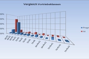
■ Favourable geological and especially hydrogeological conditions and in turn an associated short-term and mutual follow-up of the excavation classes foreseen in the construction contract (Fig. 2).
2 Outline of the driven Geology
2.1 Geological Conditions
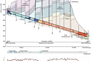
The 2,930 m (southern bore) and 3,045 m (northern bore) long tunnel sections tackled by mining means penetrated middle and lower shell lime as well as upper mottled sandstone (Röt) from west to east. In the portal areas the tunnel overburden amounts to 4 to 12 m increasing up to roughly 135 m in the middle of the tunnel.
Middle shell lime was merely encountered with lower dolomite in the western portal zone. The large proportion of the western drives were formed by lower shell lime marls and limestones, which could be reutilised without restriction and avoiding complicated intermediate storage for constructing the adjoining western section.
The eastern drives mainly passed through Pelitröt (middle Röt) with partial dolomitic clay/silt stones, individual dolomite and sandstone intermediate layers ranging from a few cm to dm thick and numerous gypsum intrusions. Directly at the eastern portal zone and the cut-and-cover section underlying basic gypsums of the Salinaröt) (lower Röt) were encountered. The Röt material containing gypsum is to be stored temporarily at the eastern portal and probably transported westwards as from May 2010 after one bore is driven by mining means and incorporated in a noise protection walls there. These noise protection walls are to be covered by an at least 1 m thick cohesive protective layer for water protection purposes.
The “Leutra Fault”, a major fault zone had to be penetrated in the central tunnel section. Here the layers of lime mudstones and myophoric layers (upper Röt) were locally displaced, sheared, folded and possessed a level to inclined dip. The myophoric layers consist of clay marl, marl stone and cm-thin limestone intermediate beds. As the west peripheral fault of the Leutra Fault zone was offset by several decametres the oolithe bank zone was not encountered by the tunnel.
2.2 Hydrogeological Conditions
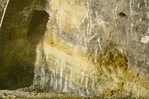
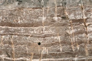
In contrast to the prognosed hydrogeological conditions of altogether 80 to 200 l/s of ingressing water during the excavation phase the incidence of underground water was slight. Even in the border zone between the groundwater-conducting lower lime mudstones and the upper Röt, damming up groundwater, and the Leutra Fault zone (longitudinal section geology, Fig. 5); the mainly seeping inflows of underground water presented no serious problems for the drive and drainage. Around the Leutra Fault between 5 and 10 l/s were forecast locally. However, at the base of the lower lime mudstones, the “yellow border bank”, karst cavities up to more than 1 m high, which indicate temporarily circulating groundwater, were revealed (Fig. 3).
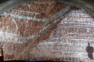
Weakly trickling underground water occurred locally mainly in the Terebratula bank zone, 2 lime banks with bank-related open lower shell lime fissures (Fig. 4).
2.3 Description of Separation Planes and Weathering
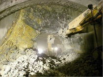
The largely unweathered to weathered rock, with calcitic separation planes in the shell lime or with fibrous gypsum in the Röt, could be driven over wide stretches in excavation class 4 without advance supporting applying only drill+blast. In the area around the southern bore close to the slope and in the proximity of the portal the clay/silt stones belonging to the Pelitröt were moistened locally along the separation planes and consequently the fibrous gypsum eluted along the bedding and fissure planes. These weathering pockets in the Röt led to locally restricted crumbling of the walls and face. This was mastered by advance spiles and effectively sealing the face with shotcrete.
Hanging parts of Pelitröt (medium Röt) prevailed around breakdown bay 3, in which the fibrous gypsum was macroscopically completely eluted from the separation planes thus leading to a substantial disaggregation of the texture (residual breccia). The face was supported by setting up a sufficiently large supporting core and spalling could largely be avoided.
The largely level bedded series of shell lime layers and the upper mottled sandstone in the tunnel section is locally folded and displaced by numerous fault paths running hercynically (NW-SE). In this connection the faults can be said to possess more or less extension character. The thrusts mainly are restricted to discrete constricted fault paths with decimetre-wide structural disaggregations. Layers of upper lime mudstones were present alongside lower lime mudstones at the eastern peripheral fault and at the western peripheral fault in the south bore, myophoric layers were to be found alongside lower lime mudstone. As a result the offset amounts at least partially lay in the decimetre range. The eastern peripheral fault in the northern bore split up into a number of individual faults with low offset amounts in the metre range. The Leutra Fault zone with a number of progressive or rift-like individual faults embraced a roughly 290 m long tunnel section in the northern bore and an approx. 275 m long one in the southern bore. These individual faults mainly ran NW-SE, subordinately linked, i.e. running NE-SW with an inclined to steep dip. An exception was formed by a rift zone of approx. 40 m within the Leutra Fault zone of the southern bore. This required a combined excavator and drill+blast drive with support core on account of an up to max. 6 m wide pronouncedly weathered to disintegrated fault breccia.
3 Effects on the Excavation
3.1 Addition Exploratory Drilling for the Leutra Fault
In the central tunnel area a number of tectonic fault paths were prognosed, which ran together to form the main fault zone, the “Leutra Fault”. Within the framework of prior investigation (design planning) up to 7 m thick fault breccia were drilled around the fault zone and offset amounts in the decametre range derived from them. In addition high underground water flows of up to 10 l/s were predicted on account of the water-damming influence of the upper Röt to the east of the fault zone to the waterconducting lower lime mudstone located above prevailing in the western fault zone area. For the “Leutra Fault” area a large number of special measures were foreseen for the excavation in the construction contract based on the forecast. These included the following measures:
■ Up to 15 m long exploratory and drainage drillings
■ 2 Advance supports using
8 m long IBO spiles up to 15 m long pipe umbrellas (d> =
139 mm)
■ Face supports with shotcrete and up to 15 m long anchors
■ Immediate ring closure in the crown by means of a temporary crown base and a base closure following directly in the bench
■ In excess of 300 m advance headings in the crown area (southern and northern bores).
Two additional horizontal drillings (core drillings) were commissioned from the tunnel by the client following extensive discussions. This was done to better estimate and possibly more precisely delimit the geological and hydrogeological development of the main fault zone and its position as well as its influence on the technical effects of tunnelling Previous supplementary geophysical investigations undertaken from the surface provided no indication of major karst phenomena although it did become evident that the eastern peripheral fault of the main Leutra Fault was displaced by some 130 to 180 m towards the east.
The 128 and 145 m long horizontal drillings (cable tool drillings), which were sunk from the crown of the northern bore in the west in conjunction with the excavation, possessed a good core quality throughout and merely revealed constricted karstification and fault zones. In spite of the striking change in rock from the groundwater-conducting lower mudstone lime marl and limestones to the groundwater-damming clay marls and marl stones of the upper Röt and the unfavourable dipping of the beds in the direction of the fault zone only ingressing seeping water was recorded by the horizontal drillings.
On the basis of these drilling results it turned out possible to renounce the complex and time-consuming support measures foreseen at the planning stage, which were previously undertaken.
3.2 Decoupled Bench and Base Excavation, Crown Base eliminated
The consequences of the changes in the affected geological and hydrogeological conditions with the inclusion of the extensive geotechnical measurements accompanying excavation inevitably led to the excavation classes foreseen in the construction contract being modified (Fig. 5). As a result it was possible to renounce the following interdependencies and support agents apart from at the tunnel entrance zones and breakdown bay 3 located in the “Leutra Fault”:
■ The temporary crown base as well as the face anchors apart from the tunnel entrance zones in all further areas originally intended
■ Decoupling the base closure (ring closure) that was foreseen in conjunction with the bench drive. The bench excavation could be executed without the base slab directly following. It was merely necessary to alternately install the bench and base at breakdown bay 3 (“Leutra Fault”) in the northern and southern bores.
4 Gypsum Problems in Röt
The gypsum intrusions in the Röt (upper mottled sandstone) place high demands on producing the subsequent inner shell (Fig. 6). Chemical analyses of the clay/silt stones with gypsum intrusions carried out during the construction period came up with sulphate contents in the material, which are to be classified as exposure class XA 3 and higher according to DIN 4030. The groundwater analyses and eluate regulations indicate an exposure class XA 2 according to DIN 4030. As the ZTV-Ing foresees an all-round seal for degrees of attack as from XA3, it was originally assumed that a base slab or a base invert would be necessary. Following protracted and intensive discussions and taking all risks into consideration the client decided to relocate the contractually foreseen base invert from the shell lime area into the Röt as well as to add a further 620 m of base invert in the Röt.
As a consequence an umbrella shield with open base is provided for the “dry” Röt areas and the Röt areas with documented underground water inflows accompanying the excavation receive a base invert with all-round seal so that the tunnel can be executed within the foreseen framework conditions as laid down in the construction contract.

