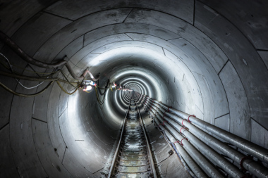
Emscher Interceptor: Special geotechnical Tunnelling Features in Section 40
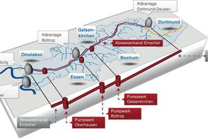
Since the period of industrialisation, waste water in the Ruhrgebiet has been drained into the east-west River Emscher. In order to restore the natural condition of the Emscher and its tributaries, work is underway on the project „Emscher Conversion“ to collect the waste water and run it to four treatment works in closed sewer tunnels. The overall project between Dortmund-Deusen and the mouth of the Emscher in Dinslaken includes the new construction of about 400 km of sewer tunnels, four treatment works and three pumping stations. The largest individual project is the Emscher Interceptor (Abwasserkanal Emscher/AKE), which runs about 51 km in the immediate vicinity of the Emscher.
1 Introduction
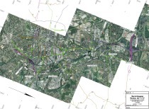
The Emscher Interceptor AKE (Fig. 1) has an internal diameter of 1.6 m to 2.8 m and is being constructed at depths of up to 40 m. Both pipe jacking and tunnel boring machines were used to construct the AKE. Due to the size of the overall project, the works were awarded in several construction sections.
The route of the sewer largely runs through various Cretaceous strata (Bottrop beds, Osterfeld beds and Emscher marl), with the Emscher marl predominant. The stronger zones in the cretaceous show the properties of a half-strength rock. In the western construction sections, the marl mainly behaves as a cohesive soil.
2 Route of the Tunnel
Construction section 40 (BA 40) was awarded as a double tunnel with a length of about 10 km to an internal joint venture of Porr Bau GmbH and Porr Deutschland GmbH. Since the sewer tunnel is designed as an unpressurised sewer with a fall of 1.5 ‰, it is about 25 m
below ground level at the starting shaft (Shaft SD.033) and about 40 m deep at the target shaft, the pumping station in Oberhausen (PW OB).
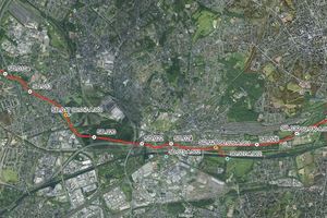
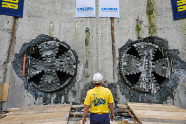
The tunnels with a clear diameter of 2.6 m were bored by two shield machines with active earth pressure support, with an external diameter of about 3.4 m (cf. [2]). The horizontal spacing between the two tunnel tubes is about 6.2 m. In the course of the tunnel drive, nine previously constructed main shafts were passed through and the Autobahns A42, A3 and the above-ground Emscher Canal were crossed several times (Fig. 2).
3 Geological Conditions on BA 40
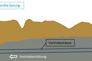
In order to investigate the ground conditions in the area of BA 40, about 300 boreholes were drilled to a depth of about 70 m between 2003 and 2010 and cores were taken for laboratory investigations, including the laboratory of ELE Beratende Ingenieure GmbH. The information gained mostly showed Quaternary soils under the fill, predominantly with underlying cohesive soils such as marl. Fig. 3
shows the systematised, geotechnical longitudinal section of construction section 40.
Various types of marl can be distinguished along the route of construction section 40. The Emscher marl is the predominant deposit and consists of glauconitic, calcareous, clayey silts and calcareous silty fine sands, which are consolidated to clay or sand marl and clay or calcareous marlstone. Above the Emscher marl are the Osterfeld beds, which consist of silty and marly fine sands, mostly with a considerable medium sand content, as well as very sandy silts. The Bottrop beds, which partly overlie the Osterfeld beds, consist of grey-green glauconitic fine sand marlstone, which transitions at the base to marly fine to medium sands. The upper part of the Bottrop beds consists of fine sandy clay marlstones and marlstones. At its surface, the marl is mostly weathered and softened. The Cretaceous beds dip flatly to the north northwest. Additional tectonic faults lead to all these Cretaceous strata being passed through by the tunnel drive.
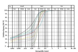
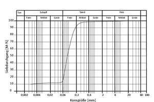
It was also found that the tunnel drive partially lay in a Tertiary fault zone (see Fig. 3). This fault zone is known as the „Concordia-Sprung“ and is characterised by a very high sand content. As a result of the laboratory tests, the fault zone material was described as silty sand. Fig. 4 shows the grain size range of the Cretaceous ground passed through in the west half of BA 40 and the grading distribution of the material of the Concordia-Sprung.
The fault zone showed a length of altogether about 200 m in both tunnel drives. Driving from the east to the west, the proportion of sand in the face increased until the entire face was sand. At the end of the fault zone, the marl horizon rose in a jump, so greatly changed geological conditions were encountered in a relatively short distance.
4 Process Technology used
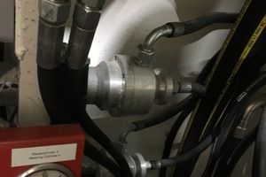
Two tunnel boring machines from Herrenknecht were used to bore the two tunnels. The earth pressure balance machines with segment lining had one of the smallest diameters in the world at 3.4 m and a length of about 14.5 m. The entire length of each tunnel boring machines including backups was about 90 m, which resulted in a total weight of 260 t for each machine. Due to the extremely restricted space, the components necessary for the operation of the earth pressure machines were kept as small as possible and distributed along the backup. In order to ensure adequate soil conditioning, four foam generators from MC Bauchemie were installed in each shield machine (Fig. 5).
These have the feature that air is fed into the liquid flow through a membrane to produce foam with defined bubble diameters. Tenside foams were mostly used as the conditioning agent. The foam could be pumped through the pumped pipeline to the face, into the excavation chamber and into the screw conveyor. With the injection of foam, the soil could be conditioned to give the support medium and the excavated material adequate workability.
The excavated material was transported from the discharge of the screw conveyor on a conveyor belt in the upper part of the tunnel section and discharged into three tubs. The filled tubs were taken back to the starting shaft after every advance, lifted out with a crane and emptied onto an intermediate stockpile. Due to the geotechnical properties of the material, no recycling of the excavated material was possible.
The process required an annular gap of 15 cm. This was continuously filled with two-component grout, particularly due to the logistic and technical advantages.
5 Experience from the Construction Period
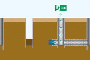
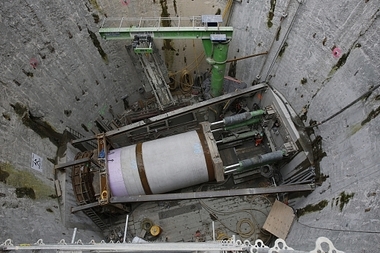
The two machines started work in October 2014 and reached the target shaft at the later pumping station in Oberhausen in June 2017. For safety reasons, the earth pressure machines were stopped after passing through the shafts, in contrast to the original plan (see [3]). Then the shafts were opened to ensure the shortest possible escape route (Fig. 6) from the shield machines in case of an emergency.
In the marl, an average advance rate of 65–70 mm/min was achieved. Through the Concordia-Sprung, a slower advance rate of about 55 mm/min was intentionally chosen, with an average support pressure of up to 2.5 bar, in order to be able to react to any challenges during the drive and minimise settlement at the surface.
Out of the four foam generators on each machine, only two were needed for most of the time in order to produce a sufficient quantity of foam of adequate quality for the tunnel drive. In the marl strata, a foam with a foam expansion rate FER of up to 6 and a foam injection rate FIR of 140 were used (see [4]). Passing through the Concordia-Sprung in the silty sand, foam with a FER of 7 was injected into the ground.
During the drive of the southern machine in the area of the Concordia-Sprung in March and April 2017, the grading distribution of the investigated material was tested. This showed the soil encountered to be silty fine sand and agreed very well with the results of the site investigation carried out at points in advance of the drive (Fig. 7).
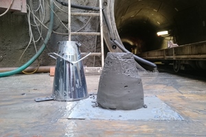
Furthermore, in March 2017, samples of the material excavated from the Concordia-Sprung were taken from the tubs of an advance in the south tunnel. Due to the flushing process during ring installation, the material transported at the start of an advance stroke showed soft properties, while the material from the end of an advance stroke of 1.20 m length had considerably stiffer properties. The excavated material was slump tested on site (Fig. 8). This showed that material excavated at the start of a stroke had a slump of about 20 cm while the material from a later stage of a stroke had a slump of about 5 cm.
These figures correspond very well with the requirements for an adequate support medium – specified as a slump between 10 cm and 20 cm – according to [5]. Fig. 8 shows the test to measure the slump on the silty sand of the Concordia-Sprung.
The excavated material with a total volume of about 180 000 m³ was largely loaded onto ships and used for recultivating gravel quarries.
The to earth pressure machine reached the target shaft at the later pumping station in Oberhausen on 12 June 2017, three months before the originally planned date; each machine had covered a distance of more than 10 000 m.
Literatur/References
[1] Ketteler, R.; Göbl, A.; 2015: Maschinentechnik, Baustellenlogistik, Bauausführung und Sicherheitstechnik beim parallelen Auffahren kleiner Tunnel (DN 2600) im Schildvortrieb, Forschung & Praxis 46, STUVA Konferenz 2015, Dortmund, S. 243–247.
[2] Machentanz, C.; 2016: Abwasserkanal Emscher – Bauabschnitt 40: 20 km Tübbingvortrieb für eine saubere Emscher in Oberhausen, Special Kanal- und Rohrleitungsbau, Ernst und Sohn, S. 6–10
[3] Stratemeier, N; Schockemöhle, B.; 2017. Interceptor along the
Emscher – Successful implementation of a major project for the structural transformation in the Ruhr area using the smallest EPB TBM in the world, Proccedings of World Tunnel Congress 2017, Bergen, Norwegen
[4] Kleen, E.; Budach, C.; Hörlein, N.; 2017: ”Successful EPB-Tunnel Drives with Conditioning Agents based on Laboratory Research“, Proccedings of World Tunnel Congress 2017, Bergen, Norwegen
[5] Budach, C.; Thewes, M.; 2013: Erweiterte Einsatzbereiche von EPB- Schilden, Geotechnik, Volume 36, Heft 2, S. 96–103

