Mechanical and process-technical Characterisation of the Rock influenced by interactive Behaviour of Machine – Ground
This article presents a model to describe the ground for excavation using tunnel boring machines (TBMs) taking process-technical and engineering criteria into account. By simulating the individual part-processes of a TBM drive and the resultant effects on the loosened rock, it is proposed to obtain indices for evaluating the potential for change and the characteristics of the changed rock. In addition it is intended to provide an appreciation of the effects of the changing processes on driving.
1 Introduction
In the case of TBM drives the excavated material is subject to numerous processes of change while being extracted by the cutting wheel right up to being discharged at the portal, which for instance can considerably influence the TBM’s rate of advance as well as follow-up working phases such as e.g. transport and the further use of the excavated material (reuse/dumping). In this connection the parameters adhesiveness, abrasivity and internal friction as well as the transformation to paste of the loosened rock are concerned.
The effects of these processes of change on the one hand depend on the properties of the prevailing rock (rock properties and ground water conditions) and on the other on the applied process technology and the mode of operation and usually are very difficult to evaluate and only to a limited extent at the planning stage.
In the case of EPB shield drives in particular (SM-V5) the usual procedure involves attempting to produce a paste from the loosened rock in the extraction chamber by adding water and other conditioning agents such as e.g. foams and bentonite suspensions thus causing the properties to change radically.
As far as rocks are concerned above all clay, silt and marl rocks reveal a high potential to change, which is to be established among other things through “water storage tests”.
For evaluating process-related processes of change for the loosened rock as well as their effects on the individual working steps of the TBM, normative classification of the rock is only sufficient to a limited extent as the essential influence of design (including process technology, form of cutting wheel) and mode of operating (e.g. control system, application of conditioning agents) of the TBM, cannot be normally considered relating to the ground.
2 Process-technical relevant interactive Mechanisms Machine–
Ground
The significant interactive mechanisms between the ground and TBM are wear, adhesiveness and transformation to paste, which depend on many influences and parameters, which cannot be collated and classified in their entirety.
2.1 Wear
Wear is described as abrasion on the surface (material loss) of mechanical parts of the TBM on account of strains resulting from extraction, crushing and transportation of the rock. As far as the rock characteristics are concerned the hardness and strength of the rock exert the greatest effect on the wear as well as the granular distribution, the grain form (angularity) and roughness of the grain surface in the case of soft ground.
2.2 Transforming to Paste – Potential for Change
The transformation to paste represents the targeted alteration of the loosened rock in the extraction chamber in order to produce a plastic earth paste as supporting medium for the face during an EPB shield drive. Creation of an earth paste with the required properties is directly related to the potential for change of the rock, which can be influenced by adding water and conditioning agents. The membrane characteristics are determined by the percentage of fine grain in the grading curve, which is largely governed by the TBM’s mechanical intervention during loosening (cutting wheel), mixing and conveyance (extraction chamber) with respect to intensity and duration.
2.3 Clogging
Clogging denotes the strong adhesion of excavated material on mechanical parts or clumps formed as a result of cohesion, which e.g. can cause inlet openings of the cutting wheel and conveyance channels to become clogged. Adhesiveness can be expected in cohesive soft ground and in changeable solid rocks.
Clogging on the cutting wheel and in the extraction chamber is usually caused by a high fine grain content, which for its part leads to diminished rates of advance (“clay fragment”) as well as being accompanied by increased (secondary) wear and a greater need for cleaning. Obstacles affecting driving as a result of these mechanisms can so far merely be estimated in general in the course of planning owing to a lack of normative regulations.
2.4 Changeable solid Rocks
Changeable solid rocks such as e.g. clay, silt and marl rocks possess a special significance when considering the effects of inter-active mechanisms, as they have a high potential for change. The potential for change depends on a large number of parameters, such as e.g. the compressive strength, the pore volume, the swelling capacity, the grain distribution and the grain bond. On account of an extremely low or non-existent mineral bond the structure of these rocks tends to disintegrate as a result of mechanical strains and/or contact with water. Solid rocks, which originally were sampled and assessed in accordance with rock mechanical characteristics, are reduced to their original granulations or at least in part to sticky conglomerates, which are to be assessed as soft ground in terms of rock mechanics.
A clay rock addressed and tested as a solid rock at the planning stage can be transformed into a soft, sticky, thoroughly plastic clay as a result of processes based on technical procedures. During the execution of construction the aforementioned difficulties in driving ensue. The processes of change are known; however a precise qualitative assessment of the consequences for driving based on a large number of factors of influence has so far provide to be rather difficult.
Although the conventional codes of standards for characterising solid rock foresee a rough distribution of the rocks into variability classes, the properties of the changed rock have still not been dealt with. For the application of earth pressure balance and hydro shields given changing solid rocks it is essential to arrive at a more far-reaching characterisation of the ground taking mechanical and process-technical aspects into consideration.
3 Laboratory technical Examinations to characterise the Ground
The EN norms distinguish between solid rock (EN ISO 14689-1) and soft ground (EN ISO 14688-1 and EN ISO 14688-2) for characterising the ground. Depending on the ground type various geotechnical lab tests are carried out. This is on the one hand because different “key parameters” to describe the rock characteristics are of interest and on the other that certain tests can only be executed given corresponding samples. A further factor for determining the geotechnical lab tests is represented by the aim of the investigation depending on the planned intervention.
The following rock properties are of interest for performance and wear prognoses for TBM drives:
• rock strength
• rock abrasivity
• changeability/potential for change
• adhesiveness
3.1 Rock strength
The rock strength is established by means of uni-axial pressure tests. Furthermore in keeping with the project in hand Brazilian tests, point load tests and tri-axial pressure tests are undertaken. Additionally in conjunction with fine grained soft grounds it must be observed that the strength greatly depends on the consistency and varies with the water content.
3.2 Rock abrasivity
The rock abrasivity as the means to estimate the wear is usually established with the Cerchar abrasivity test for solid rocks and with the LCPC test for soft grounds [4]. The determination of the equivalent quartz content can be taken as an additional means of estimating the wear.
3.3 Changeability/Potential of change
In order to assess the changeability of the rock the European Norm EN ISO 14689-1 as well as national standards based on it (e.g. DIN EN ISO 14689-1, ÖNORM B4400-2) foresee water storage tests.
Back in 2005 M. Nickmann examined problems in executing and evaluating water storage tests in the publication “Investigations to classify variable solid rocks under engineering-geological Aspects” [1]. He arrives at the conclusion: “All in all it is shown that the water storage test is not suitable to adequately collate and classify the behaviour of variable solid rocks”. In the case of drum screening tests and Slake durability tests the relatively high technical outlay and above all the execution of the tests with dried material, which fails to correspond to the “in situ” conditions are negatively rated. The modification presented in the above-mentioned publication relating to the water storage test based on a threefold drying-wetting changeover, represents a substantial improvement for classifying variable solid rocks. The strain resulting from the 3 changes however usually does not suffice to cover the strains, which result during a TBM drive through extraction, splitting and conditioning processes.
3.4 Adhesiveness
Adhesiveness is not explicitly dealt with in the norms. Approaches on this topic are partially to be found in works contract norms although they do not go beyond visual appraisals and general statements. In the ÖNORM B2205 “Earthworks – Works Contract Norm” adhesiveness is defined e.g. as follows: “An adhesive consistency prevails when the soil on the shovel or spade can only be removed from the tool with the aid of a further appliance (scraper or the like)”.
When being used in practice the evaluation diagram according to Thewes (1999) [2] is often applied to assess the clogging potential of soils. By means of the initial parameters (consistency number Ic and plasticity number Ip) the investigated soil can be allocated a low to high adhesiveness potential (Fig. 1).
The plasticity and consistency numbers can be ascertained with the help of the natural water content and the Atterberg limits (plastic limit and liquid limit). It is only possible to ascertain the liquid and plastic limits in the case of cohesive soft grounds. Thus it is impossible to assess the adhesiveness potential of variable solid rocks on samples. As a prerequisite the core sample embodying the solid rock properties must be prepared and reduced to its sedimentary original granulation. The standardised soil-mechanical lab tests to ascertain the grain distribution curves as well as to determine the natural water content and the Atterberg limits can be carried out on the prepared samples.
The clogging diagram according to Thewes only allows coarse estimates of the clogging potential of the subsoil for TBM drives, as first of all the grain distribution of the fragmented sample material can spread depending on the intensity of fragmentation. Secondly only a representative value as possible can be applied for the water content as a significant parameter for determining the consistency number. During the application of shield machines the natural water content of the “in situ” rock is altered through ingressing ground water (especially during TBM standstills), the addition of conditioning agents and process waters and cannot be prognosed. The method of operation of the TBM and the percentage of clay materials with the capacity to swell represent other factors, which influence the adhesiveness of the loosened material.
4 Strategy Model for mechanical and process-technical Characterisation of the Ground from Excavation to Discharge at the Portal
4.1 General
As already indicated the normative regulations for describing the ground in “in situ” state consider this regardless of the planned TBM deployment. The determining of changes in the rock properties as a result of strains during the individual working stages of a TBM is not regulated and up till now can only be roughly estimated. This circumstance is evident particularly in the case of changing solid rocks. The following strategy model is presented for appraising possible effects in a better manner.
4.2 Basis of the Strategy Model
The conditions actually prevailing during the drive cannot be precisely reproduced technically in tests. The given model is an attempt to supply additional information for project-specific estimation of the effects of the changed excavated material.
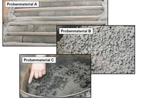
Through a gradual approach ground types, means of operation (above all operating modes) and processes relating to the application of the TBM are extracted, during which obvious changes of the excavated material take place. Subsequently rock samples are examined, in different forms in each case. Freely defined pretreatments of the samples enable the effects of the alterations to the state of the rock brought about by process technology under the inclusion of normed lab conditions and supply additional information to estimate the properties of the excavated material in the various part-processes of the TBM.
4.3 Set-Up of the Strategy Model
Based on the geological, hydrogeological and geotechnical ground model the relevant ground types for the examination have to be selected as well as establishing the corresponding prognosed ground water ingresses.
A frame for the examination must be established for the project, which can range from appraising individual relevant part-processes (e.g. closed mode of an EPB shield machine) of a sector for a certain ground type right up to numerous combinations of types of rock and part-processes. Given a corresponding amount of data sensitivity analyses relating to the processes of change depending on time, ground type, mechanical strains, the added amount of water, the type and quantity of conditioning agents and further parameters are possible.
The following steps should be undertaken for each part-process:
1) Estimating the possible strains and marginal conditions for the determined sector and part-process.
2) Pretreatment (crushing, adding water and conditioning agents, thorough mixing) of the sample material with the simplest means possible to simulate the strains and marginal conditions.
3) The process-technical determining properties of the excavated material such as consistency as well as the corresponding parameters (e.g. water content) must be collated.
4) Execution of the standardised lab tests such as uni-axial pressure test including the normative sample preparation (e.g. cylindrical samples from a drill core) to ascertain the parameters of the pretreated sample material.
The individual steps are to be executed and documented in such a fashion that the pretreatment of the samples can be exactly reproduced at any time.
4.4 Applying the Strategy Model taking the Example of an EPB Shield Drive
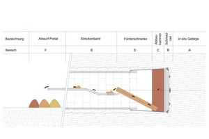
The strategy model is applied exemplarily on an EPB shield drive. The TBM is split up into 6 sectors according to Fig. 2.
Only the closed mode is lent consideration in the following, as the hardest strains can be expected here on account of the loosened rock turning into paste as a result of ingressing ground water and the addition of conditioning agents. The demarcated part-processes A to F will be examined in the following.
Sector A – “in situ” Rock
“In situ” rock is defined as the rock, which is located outside the drive’s sphere of influence. This applies to both influences of stress redistribution, the ground water situation and the penetration depth of the means of supporting the face. As a result the “in situ” rock in many cases ends before the face.
System-related Strains: none.
Sector B – Cutting Wheel
System-related strains: an initial cutting process with the cutting wheel or rather with the applied extraction tools takes place when the TBM is introduced into the ground. The set of tools is geared to the project conditions and largely governs the extent of fragmentation.
Sample pretreatment: fragmenting the core sample in the form of the expected excavated material, e.g. as chip fragments with a defined size. Abnormalities such as e.g. fracture behaviour, prevailing fine grain percentage etc. must be exactly documented.
Sector C – Extraction Chamber
System-related strains: mechanised fragmentation and homogenisation of the excavated material (earth paste) takes place with the aid of stators, rotors and the cutting wheel’s rotary movement. Further plastification of the excavated material occurs through ingressing underground water as well as the controlled addition of conditioning agents.
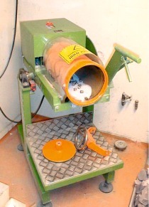
Sample pretreatment: the chip fragments won from the core samples (please see sample treatment B) form the starting material. Water has to be added in keeping with the prognosed ingressing ground water geared to the sample quantity and the targeted addition of water during the driving process and the continuing addition of conditioning agents. The homogenisation and plastification of earth paste can e.g. be simulated in a paddle mixer, with the degree of mixing being documented by the duration and rpm etc.
Sector D – Screw Conveyor
System-related strains: the screw conveyor causes a further mechanical strain on the excavated material. The earth paste is dammed up and compacted for the necessary forming of a plug given the closed mode to establish a pressure level at the screw conveyor’s closure device; pore water is partially pressed out.
Sample pretreatment: the starting material forms the earth paste (please see sample treatment C). The process water can e.g. be pressed out of the earth paste e.g. with the help of a filter press set at a defined pressure level.
Sector E – Belt Conveyor
System-related strains: no additional strain is anticipated on the belt conveyor.
Sample pretreatment: none: sample material corresponds to sample pretreatment D.
Determining material properties and test programme: please see Table 3.
Sector F – Belt Conveyor and Discharge at the Portal
System-related strains: once more a mechanical strain as well as a certain sorting process concerning the banked material occurs during discharge at the portal. However the latter is largely remedied during the loading process for further using the excavated material.
Sample pretreatment: none; sample material corresponds to the sample pretreatment D.
Determining material properties and test programme: please see Table 3.
As assistance for estimating a possible further application of the excavated material (e.g. reutilisation for fills) examinations and lab tests such as determining the water content, Proctor tests, shear and compression tests can be undertaken on the basis of the pre-treated sample material. These test evaluations also provide indications for the effectiveness of possible stabilisation measures (e.g. with burnt lime) (Fig. 3).
5 Attainable Results
The following results are attainable with the described strategy model and applicable both in the choice and invitation to bid for the driving concept, during the execution of construction and the material management and processing:
• Identification and minimising possible risks relating to the ground and methods [6]
• Clarification of the allocation of competences when bearing risks
• Devising the best possible driving modes
• Specification and optimising the applicable driving and mucking system
• Catering for added difficulties and accounting
• Optimisation of material management and material processing in conjunction with the genesis during the excavation and conveying process
• Objectivising the complex interaction between ground, groundwater and driving.
6 Outlook
As the present strategy model that has been described is based in part on assumptions of the input data, these have to be verified by samples from the individual part-sections/processes of the TBM and process-technical data (e.g. the amount of conditioning agents added) during driving. Through the described systematic approach applied in the strategy model as well as the comparison and analysis of practical experiences the basis has been created for future projects, which can enable an improved estimation of the effects of TBM driving on the excavated material thus supplying a helpful contribution to planning TBM drives in variable solid rocks.

![Clogging potential depending on plasticity and consistency for fluid-supported shield drives after Thewes (1999) [3]](https://www.tunnel-online.info/imgs/tok_422630b360f7701fa83d145017407407/w300_h200_x400_y289_100834199_2d8bf369e9.jpg)
