Tunnels in the Lausitz Lake District
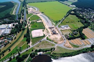
Europe’s largest artificial lake landscape and a new tourist region are being created where formerly excavators won brown coal by opencast mining: the Lausitz Lake District. Ten lakes in its core area will be linked by 13 canals to make them negotiable by ship. The Lausitzer und Mitteldeutsche Bergbau-Verwaltungsgesellschaft (LMBV) has already completed 3 canals. A further outstanding project being tackled by the LMBV since February 2009 – as a tourist infrastructural project on behalf of the Land of Brandenburg for the town of Senftenberg – is the so-called conductor 12 from Lake Senftenberg to Lake Geierswald. Sports boats and passenger ships will ply on the canal.
Tunnels run under the B96 and the Black Elster
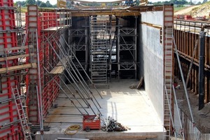
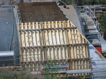
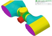
The 1,050 m long canal has a 6 m floor width and a 2.5 m minimum water depth. From west to east it undercrosses 2 obstacles in 2 imposing tunnels: the federal highway B96 and the future bed of the Black Elster. The river is to receive a new course because it has to make way for a lock, which is being built to compensate the difference in elevation between the 2 lakes (Fig. 1). The 2 tunnels are produced by the Ed. Züblin AG using Meva formwork. They are rectangular structures built by cut-and-cover with 7 m clearance height and a 7.5 m clear width including a rescue path at the side. Wing walls extending at a degree of 30° at each side close off all the tunnel ends. The tunnel beneath the B96 is 56 m (Fig. 2) and the one below the river 90 m long.
Tunnel Walls shuttered with large-area Units
The tunnel fundaments were shuttered with Mammut formwork. The walls were provided with Mammut 350 formwork with a height of 350 cm. The height of 7 m was achieved with only a single extension. Several elements were combined to form large-area units. In this way the shorter tunnel could be shuttered with seven 8 m and the longer one with ten 8 m cycles and a 10 m one. The complete units were moved by crane in order to save time.
Exposed concrete was called for in the case of the tunnel walls. As the anchor points for the applied elements were set up in a strictly symmetric order, a uniform anchor and joint pattern was attained without difficulty. The full plastic panel Alkus, which has been in use for years, catered for a uniform concrete surface.
Wing walls with multi-tapered Cross-Section
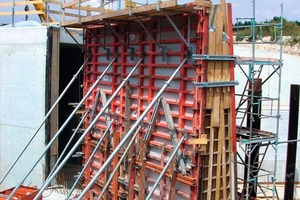
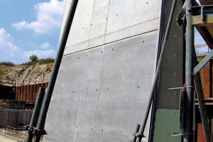
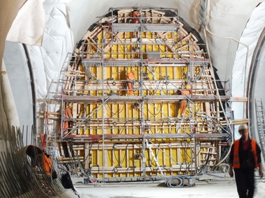
The fundaments of the wing walls were shuttered with Mammut formwork and inclined struts. The roughly 21 m long wing walls rise up to the tunnel walls. In addition the wall thickness is tapered from the bottom to the top by 6 degrees at the side facing the water (Fig. 3). In addition each wall becomes narrower towards the tunnel for structural reasons – with a ledge roughly every 6 m on the outer side, which is subsequently backfilled with earth. The wing walls are up to 1.50 m thick at their base tapering to become 0.54 m at the top. They were shuttered with Mammut and Mammut 350 elements – involving a new cycle for each ledge. The incline was attained using sloping elements – except for the connecting pieces between the wing walls and the tunnel walls. No sloping formwork could be employed here for geometrical reasons. Vertically installed elements with inserted formwork were used, which were covered with full plastic panels. The wing walls were also produced in exposed concrete quality (Fig. 4). Tapering and the various large elements called for careful planning for a symmetrical anchor and joint pattern.
Ceiling Formwork Car saves much Work and Time
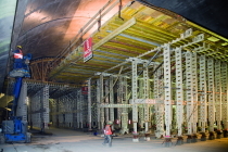
Per tunnel the ceilings were shuttered by means of 3 to 11.80 m long ceiling tables. Each table comprises H20 full wall timber beams and a MEP support frame. The components were connected to form a single mobile ceiling formwork car using scaffolding tubes and 4 frame arms rather than lose time by having to dismantle and reassemble them again for each cycle. It was possible to pull the entire construction to the next cycle without taking it apart and putting it together again. The advantage for the site: the formwork car could be built using standard parts without expensive special parts having to be used for the short space of a few weeks when they were required.
Completion in 2012
Once the above mentioned activities are completed the tunnels will be backfilled on the outside. Then the federal highway will be constructed above the western tunnel and the new river bed produced above the eastern one. During 2011 constructing the lock will take up most of the activities. Work is due to be concluded in mid-2012 once landscaping and roads have been completed so that the first ship should be able to pass through the canal in 2012.

