Deformation-Tolerant Tunnel Linings in Swelling Soils
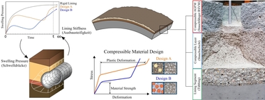
Mechanized tunneling in difficult geological conditions, such as soils with significant swelling potential due to water uptake by the clay minerals, depends not only on the calibration of the tunnel boring machine to the ground characteristics, but also on the ability of the tunnel lining to tolerate localized swelling pressures. In order to avoid the risk of damage to the tunnel lining, additional radial layers such as a compressible tunnel lining segment and a compressible annular gap grout can be included (Fig. 1). However, the deformability of a tunnel support after reaching a certain yielding load affects the distribution of the stresses and deformations around the tunnel and as a consequence determines the magnitude and buildup of the swelling pressure. Thus, the goal is to develop a lining system i.e. material design and structural design that ensures an optimal soil-structure interaction through a synergy of computational and experimental techniques.
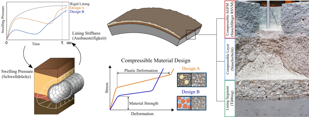 1 | Left: Tunnel-soil interaction. Middle top: Compressible cementitious layer and a compressible annular gap grout on the lining segment. Middle bottom: Typical mechanical behavior of the compressible materials. Right: Deformable tunnel lining (lining segment – compressible layer – compressible annular gap grout) with applied deformation (approx. 12 cm or 70% of the initial thickness of the compressible annular gap grout)
Credit/Quelle: RUB
1 Hydro-Mechanical Processes During Mechanized Tunnelling in Soil With High Swelling Potential
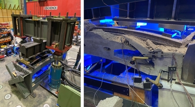
The stress redistribution, dilations and deformations in clay rocks as a consequence of tunnel excavation [1] lead to development of an Excavation Damaged Zone (EDZ) around the tunnel. The shear strain evolutions within the EDZ causes an increase in the hydraulic permeability of clay rock. If the clay rock has high swelling potential, the EDZ can act as a preferential flow path to transport the water into the vicinity of the tunnel, which triggers the swelling process. In order to predict the swelling process in the transient unsaturated state, the degree of saturation and the suction should be considered as state variables. Additionally, the interaction between the tunnel structure and swelling clay rock in terms of deformation tolerability leads to different swelling boundaries (e.g. free swelling – unsupported tunnels, volume constant swelling – stiff tunnel support and swelling under controlled volumetric deformations – deformable tunnel lining) that should be properly addressed in the numerical simulations. For this purpose, an adequate swelling law has to be developed based on swelling tests under various boundary conditions. Figure 2 shows the novel swelling test device that has been designed and built to enable conducting such complicated tests in different tunnelling relevant boundary conditions. The deformation response of the tunnel support affects the size and shape of the EDZ in swelling clay rock, which in turn influences the maximum swelling pressure and its evolution rate. Thus, design of soil-tunnel system requires an adaptive simulation that interactively considers the coupled tunnel-structure response, the EDZ shape and the swelling pressure in time domain.
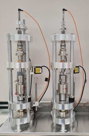 2 | Swelling test device for tunneling relevant boundary conditions
Credit/Quelle: RUB
2 Design of Deformable, Damage Tolerant Tunnel Linings
The design of a multi-layered deformable lining system involves the determination of suitable compressible materials and an optimal structural configuration of the compressible layers. This design process has to be performed in an iterative manner, taking into account the soil-tunnel interaction (Fig. 1, left). For this purpose, compressible cementitious materials were developed, which are arranged as annular gap grout and as an additional compressive layer at the exterior of the lining (Fig. 1, right). By using compressible additives (e.g. expanded glass granulate, expanded polystyrene) and highly air-entraining admixtures, a high degree of compressibility can be achieved (Fig. 1, middle). For the investigation of the material behavior, compression tests were carried out in a rigid cylinder (Fig. 3, left). By variation of the mix proportions (e.g. type of additives, air content, volume fractions, water-cement ratio) and testing parameters (e.g. transverse strain constraint, deformation rate), essential influencing factors on the compressive behavior (yielding level, compression capacity) were identified [2].
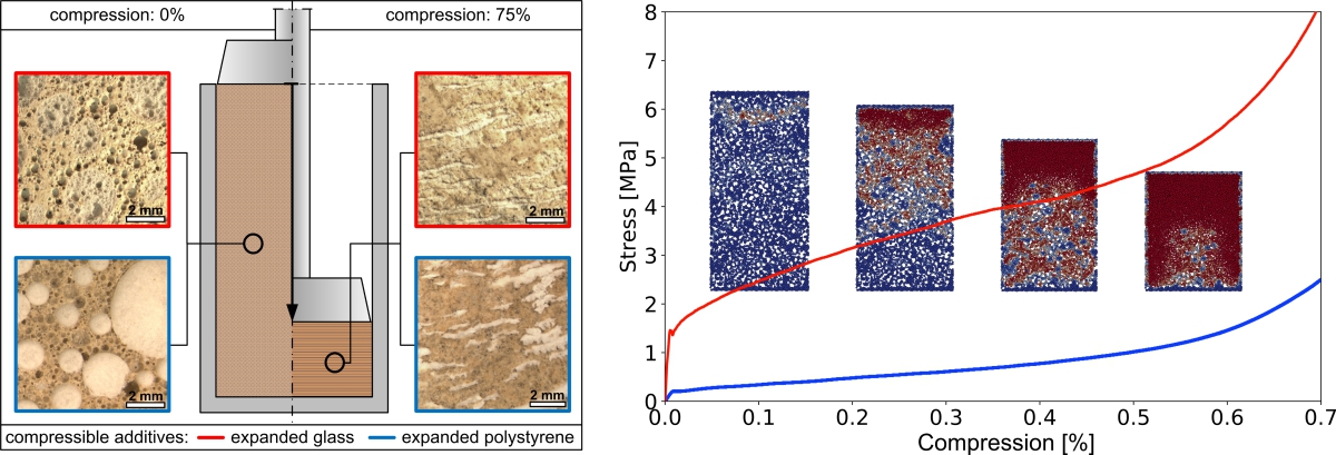 3 | Left: Experimental setup and material microstructure. Right: Experimental stress-compression curves with snapshots of the computational simulations
Credit/Quelle: RUB
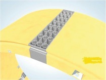
Figure 3 (right) shows the stress-compression curves of selected material compositions. However, as the geological conditions can significantly vary along and around the tunnel, the yielding behavior of the material also has to be appropriately chosen. To this end, computational simulations are used to determine the underlying mechanisms involved in the deformation process to support the design of suitable materials with required deformation characteristics. Computational simulations using the Discrete Element Method (Fig. 3, right) show that damage initiates at the top part of the sample and forms a compression band which propagates downwards, while the voids collapse due to material re-arrangement [3]. This mechanism allows for a high degree of compression without a significant increase in stress. As soon as all voids collapse, the material starts densifying. It should be noted, that annular gap materials need to satisfy additional requirements (e.g. long processing time, high flowability, rapid stiffness/strength development) and that for compressible layers on the exterior of the lining segment, adequate manufacturing concepts must be developed. On a structural level, space for the compressible layer on the lining is provided by optimizing the utilization of the whole structure by means of strengthened joints and high performance materials (HPC) [4]. The global deformation and load carrying behavior of the multi-layered lining system (segment – compressible layer – annular gap grout) is finally investigated in a newly developed testing rig (Fig. 4), which ensures realistic boundary conditions by means of a specifically designed loading system (horizontal and radial loads).
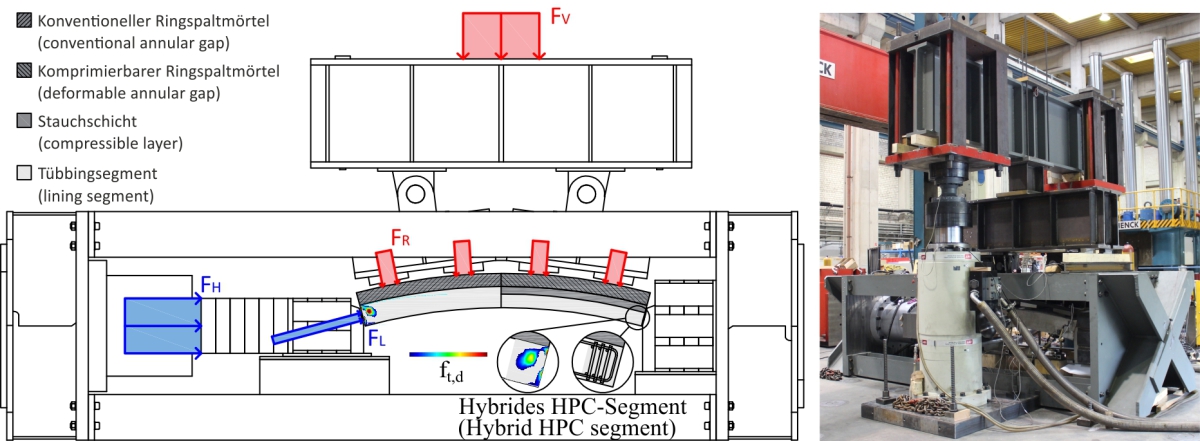 4 | Schematic (left) and picture (right) of the newly developed testing rig for the investigation of the deformation and load carrying behavior of the multi-layered lining system under realistic boundary conditions. Computational simulation results are shown for conventional (left half of the segment) and for deformable annular gap (right half of the segment)
Credit/Quelle: RUB

