Automation, Digitalization and Continuous Advance With Tunnel Boring Machines
Following key milestones in the successful handling of ever larger diameters and pressures as well as increasingly complex ground conditions, the focus is now shifting to the growing shortage of skilled workers and higher demands on quality and system performance. Digitalization and automation as well as operator supporting or autonomous systems have therefore become important development goals. In addition to these aspects, the permanent goal of improved occupational health and safety and the upcoming revision of European safety standards will also steer TBM technology toward automation. This article presents the current state of the art against the background of these special conditions.
Credit/Quelle: Herrenknecht AG
Automation and digitalization are increasingly proving to be drivers in mechanized tunnelling technology. They complement the successes achieved in recent decades in coping with more difficult ground conditions, higher support pressures, larger diameters and greater tunnel lengths as well as in increasing performance and efficiency. And they are also proving to be achievable only through discussion and cooperation between the various stakeholders – on the manufacturer and the user side.
Three drivers in particular, presented below, are determining new development approaches for mechanized underground construction:
1. Automation including artificial intelligence (AI),
2. Sustainability-focused further development of systems for the treatment of water and slurry, and
3. Intelligent data management systems.
These drivers enable further steps toward greater safety, quality and efficiency against the backdrop of the required sustainability and the lack of qualified personnel for the successful realization of tunnelling projects.
1 Automation
As an industrial process, mechanized tunnelling fundamentally offers good prerequisites for automation. Currently, two main areas of development can be observed for TBM workflows:
1. Operator supporting systems
2. Fully automated subsystems
1.1 Operator Supporting Systems
Operator supporting systems aim to partially automate recurring workflows. On the one hand, this reduces the operator‘s workload. On the other, it offers the opportunity to avoid operating errors and to integrate an interpretation aid for the current operating state of the subsystem. Current examples developed by Herrenknecht include:
Control of the tunnelling machine with display of the Center of Thrust (CoT) of the thrust cylinders and use of the same as a control variable (see tunnel 03/2024),
The needs-based filling of the sealing chambers of the tailskin seal (Adaptive Tailskin Sealing System),
Systematic convergence or overcut measurement with hydraulic cylinders that can be extended from the shield, which measure the same point of the intrados multiple times as the drive progresses and thus determine any change in the bored tunnel diameter,
Automatic control of the relay pumps in the hydraulic slurry circuit and
Automatic directional control of the back-up carriages.
In addition, the many queries, interlocks and warnings in the PLC programs of the TBM control system now taken for granted by operators should also be mentioned.
Improved TBM Navigation Through Machine Learning
Another example of the advances in operator supporting systems on tunnel boring machines is a newly developed system for laser-based machine position determination: the conventional method requires the firmly mounted total station bracket on the tunnel wall to be repeatedly repositioned following the progress of the tunnel. This results in a number of disadvantages (greater use of personnel, necessary reworking of the boreholes in the segment etc.). With the development of the
„moving station“, the total station is now positioned on the gantry and therefore no longer needs to be moved. The relocation process with its disadvantages is no longer necessary.
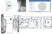
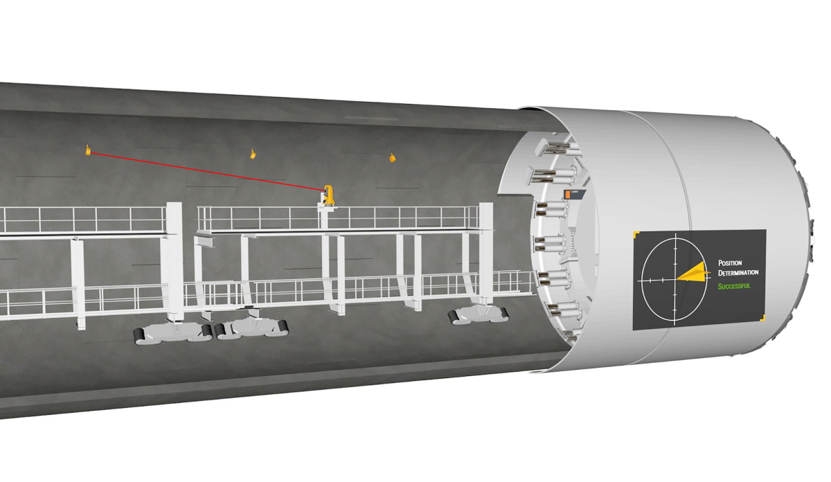 1 | Moving Station: Arrangement of the components (prisms, total station on the TBM gantry and target)
Credit/Quelle: VMT GmbH
As in the standard method, this new system also involves installing the target with its prism on the TBM and precisely determining its relationship to the machine axis. In contrast to the standard method, the total station is now mounted on the TBM gantry (Fig. 1). To determine the position, measurements are taken from the total station to prisms installed on the tunnel wall and the machine position is calculated using sensor fusion. These prisms can be moved in line with the advance with very little effort. The brackets no longer need to be bolted, but can be glued instead. There is also no need to detach and reattach cabling. The work step of removing and remounting the total station on the tunnel wall is eliminated.
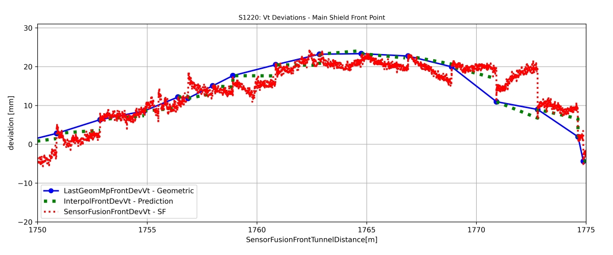 2 | Deviation of sensor fusion and geometric values
Credit/Quelle: VMT GmbH
A systemic challenge for the system with the moving station arose from the fact that it was not possible to determine the exact position during the ongoing drive. The red line in Fig. 2 shows the sensor fusion measurements, i.e. various sensor signals merged and combined to form an overall image, while the blue line represents the actual drive. The increasing error in the calculation due to the sensor fusion results in a sawtooth effect in the red line, which is caused by position jumps at the end of the advance.
To reduce these jumps in the display for the machine operator, a machine learning algorithm was developed additionally to calculate the machine position in advance (green dotted line). For this purpose, the algorithm calculates the future position of the TBM after the advance based on historical data and takes into account the data already learned (operating behavior and machine reaction) in order to be able to make more precise predictions for the next advance. Further improvements in the precision, optimization and reliability of position prediction using machine learning and artificial intelligence can be expected in the near future.
1.2 Fully Automated Subsystems
The use of fully automated subsystems offers great potential, particularly for recurring activities in TBM tunnelling. Examples include the installation of segments, the supply of segments and consumables, the removal of excavated material and maintenance of the equipment.
Segment Handling
The most frequently recurring process in mechanized shield tunnelling is the transport and installation of the segments. The focus has therefore shifted to automating these process steps for both economic and safety reasons. For long tunnels in particular, with a correspondingly large number of segments, investing in fully automated or operator supporting systems can be worthwhile.
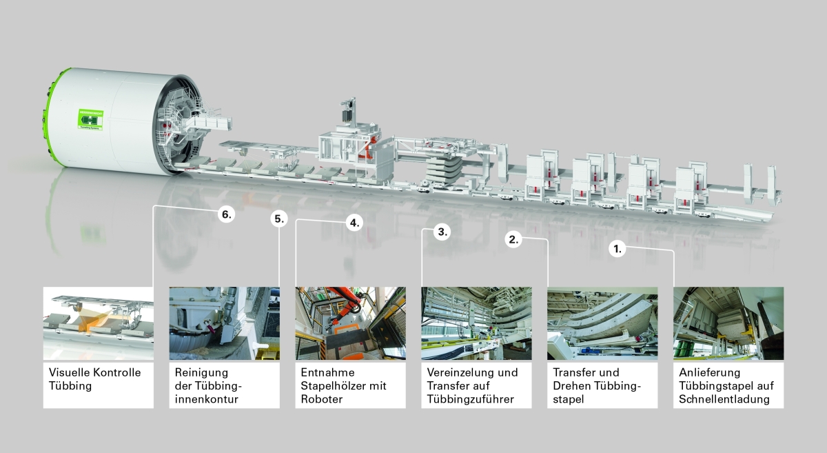 3 | Automated segment handling in the back-up system
Credit/Quelle: Herrenknecht AG
Fully automated subsystems can cover all segment handling processes from unloading the transport vehicle to picking up of the segment by the erector and ring building itself (Fig. 3). For the introduction of automated handling systems, the segments, the loading configuration and the segment stack on the delivery vehicle must be suitable for automation. While the segments are high-precision components already equipped with tools such as barcodes for automatic identification, automation increases the requirements for the geometric accuracy of the stacks, the stacking timbers and the stack position on the supply vehicle. The gripping system for segment pick-up by a transfer crane or erector can no longer include manual screwing in of segment spindles and is therefore realized by vacuum lifters or other gripping devices.
Independent of segment handling outside the tunnel portal, visual inspection of the individual segments on the TBM during unloading and before transfer to the erector helps optimize the efficiency of the processes. Visual inspection includes checking for transport damage, correct positioning of the segment seals and other fixtures as well as possible contamination of the surface (by dirt or ice/snow) that could lead to a malfunction of the vacuum pick-up. The overall system of automated segment handling also includes automated camera-based inspection systems that use artificial intelligence for image analysis, as well as preventive cleaning of the inner segment contour. Depending on the segment design and the preparation processes, an automated segment handling system can also include automated dowel assembly. Even with a fully automated system, it must be possible to transport the segments safely by hand. This includes the option of moving them from their installation position in the tailskin back onto the transport vehicle and finally out of the tunnel.
Several TBMs with a diameter of 10 m with automated segment handling in the back-up system have been delivered and put into operation in recent years.
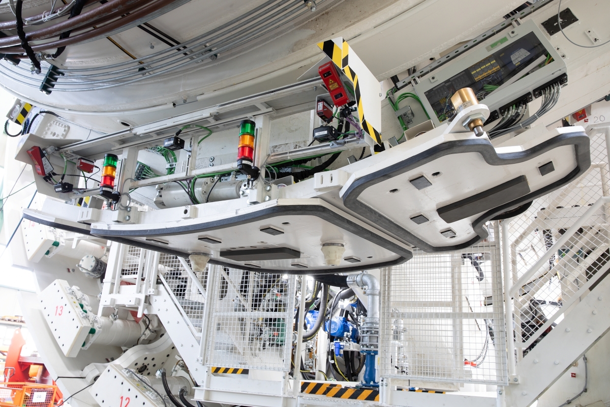 4 | Erector suction plate equipped with sensors
Credit/Quelle: Herrenknecht AG
Ring Building Support
Sensor technologies can generate additional information for the ring building process, which is either visualized directly on the erector suction plate (Fig. 4) using signal columns based on the traffic light principle or displayed on the mobile erector panel (Fig. 5), e.g. the ring building clearance or the relative position of the segment to its neighboring segments.
By providing such data to the erector operator, manual measurements no longer need to be taken from the erector platforms. In this way, safety risks can be eliminated and the number of employees for ring building reduced.
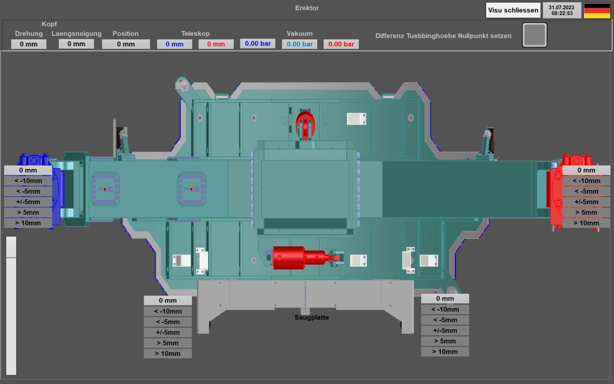 5 | Erector panel visualization
Credit/Quelle: Herrenknecht AG
Automated Ring Building
The next step beyond the provision of information is fully automated ring building. Ring building involves handling heavy precast concrete elements in an area that can be considered a confined working space, especially for small TBMs. Difficult access and limited visibility are typical challenges. Safety aspects are therefore the most important arguments in favor of automated ring building, alongside quality and cost-effectiveness, as it requires no personnel in the ring building area.
The main component of the ring building system to be automated is the erector. As with all automation processes, the exact position of all components involved must be known. All moving parts of the erector, the thrust cylinders and the segment feeder must therefore be equipped with position measuring systems.
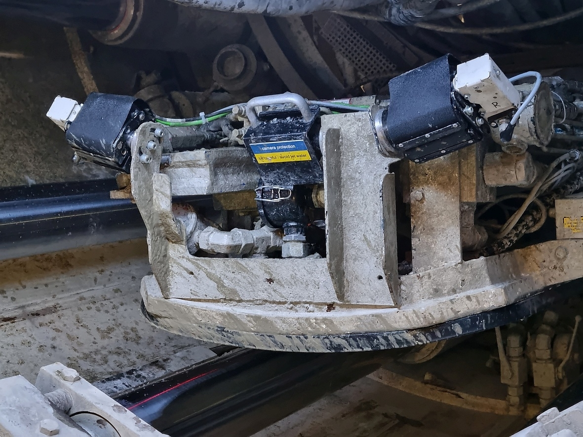
An automated ring building process requires not only the exact position of all erector functions and other moving parts, but also the exact position and alignment of the segments on the segment feeder. When using optical sensors, an unobstructed view of the sensors is essential. For this reason, unnecessary soiling of the sensors must be avoided, for example during cleaning and maintenance work on the injection lines in the tailskin. At Herrenknecht
in Schwanau, the first automated ring assembly systems for a 3 meter and an 8 meter diameter TBM were developed and tested with real-size test setups (Figs. 6+7).
 6 | Erector suction plate of a field prototype for automatic ring assembly on a 3 meter EPB shield
Credit/Quelle: Herrenknecht AG
 7 | Erector suction plate: Test arrangements of an 8 meter TBM (right) in Schwanau
Credit/Quelle: Herrenknecht AG
Once automated systems are installed, physical barriers with locked access doors must be installed to exclude access to the area with automated movement and/or handling operations. Consequently, such areas within the gantry or ring building area are only accessible during manual operation or for maintenance purposes. Automated systems thus have an impact on the working environment and workflows.
Automated systems require more sensors and computerized control systems. In particular, the harsh environmental conditions in a tunnel drive must be taken into account when selecting and designing the components. Equally, the maintenance personnel on site must be appropriately qualified.
Semi-Continuous Tunnelling
In addition to automating the sub-processes, it is worth looking at the overall process of shield tunnelling with the recurring sequence of advance and ring building to increase performance and efficiency. The tunnelling machine must be designed in such a way that the segments can be installed during the advance without the TBM having to be stopped and yet precise directional control along the route is still possible. If this is achieved, the advance rate can be significantly increased, especially for long drives. The time required for ring building is now also available for the advance. This approach significantly accelerates drives with a slower rate of advance (Fig. 8). This is because there is sufficient time available for ring building once the thrust cylinders are extended to such an extent that the installation dimension in the tailskin permits segment installation.
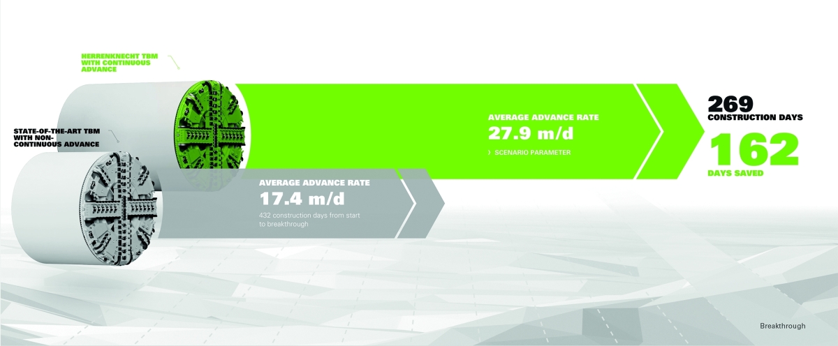 8 | Potential of continuous tunnelling for a 9 meter TBM with 1.8 meter segments and a tunnel length of 7.5 km
Credit/Quelle: Herrenknecht AG
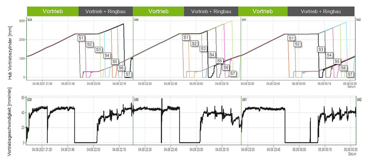
In terms of machine technology, this requires thrust cylinders with a longer stroke and a correspondingly longer center shield and tailskin as well as increased requirements for sensors and hydraulics. In the semi-continuous tunnelling concept already implemented, the tunnelling machine only stops when the required jacking stroke is reached for the installation of the first two segments. The other segments and the key segment are then installed as the drive continues.
Due to installation during the advance, the segments are subjected to higher load, which must be taken into account in the design with regard to the splitting tensile reinforcement and the verifications. The entire logistics chain of the drive should also be planned in accordance with the higher performance and the elimination of the classic ring building phase with the tunnelling machine at a standstill. This ring building phase is no longer available as at least partial possible (buffer) time for the supply vehicles or for simple quick maintenance work.
After the first deployment for the Chiltern Tunnel near London (Fig. 9), several machines with a diameter of 10 m were equipped with the system and put into operation in 2023.
 9 | Implementation of semi-continuous tunnelling in first deployment during tunnelling by shield machines for the Chiltern Tunnel
Credit/Quelle: Herrenknecht AG
2 Slurry Treatment (STP) and Water Treatment Plants (WTP)
Slurry treatment plants (STP) are used as downstream separation equipment for the excavated soil in slurry-supported mechanized tunnelling with Mixshields, Variable Density TBMs, AVNs, HDD, VSMs etc. (Fig. 10). Water treatment plants (WTP) are nowadays mandatory facilities with increasingly stringent and sustainable environmental protection requirements in civil engineering projects. They are an integral part of an efficient circular economy on the jobsite and have been developed step by step by Herrenknecht with this in mind.
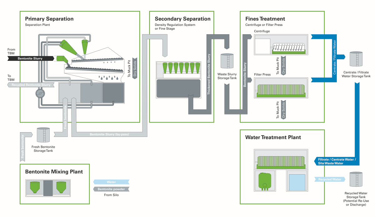 10 | Process diagram with slurry treatment (STP) and water treatment (WTP)
Credit/Quelle: Herrenknecht AG
One of these innovations in slurry treatment is the Density Regulation System (DRS), which is installed in the bypass to the primary separation circuit with screening machines and hydrocyclone stages (Fig. 11). In geologies with a greater proportion of fines, this additionally reduces or improves the separation cut and optimizes the capacity of the secondary separation. The third cyclone stage used in this process significantly increases the lifetime of the suspension. In addition, several factors increase the efficiency of the separation process, namely the thickening effect of the underflow and the discharge for ultra-fine separation with centrifuges or filter presses, as well as the reduced water content of the discharged solids. Another positive effect resulting from this is the increase in process capacity in tonnes per hour, which reduces investment costs.
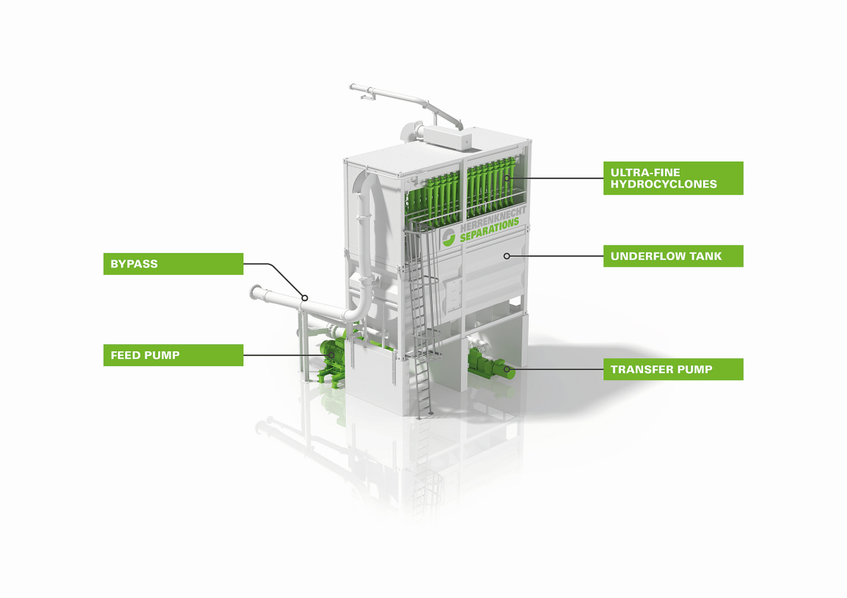 11a | Density regulation system (DRS) – in the model
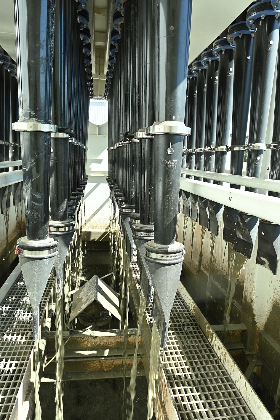 11b | Density regulation system (DRS) in use
Credit/Quelle: Herrenknecht AG
The so-called Noise and Vibration Reduction System (NVRS) was also developed to acoustically optimize the plants during jobsite operation. By means of phase shifting using hardware and software, it effectively reduces noise and, above all, low-frequency vibrations generated by the screening machines used. Residents living near the jobsite feel less affected, which increases acceptance. At the same time, the general and ergonomic working conditions for personnel are improved.
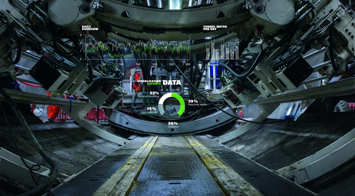
3 Data Management
During TBM operation, many processes run simultaneously. Each sub-process is monitored by sensors and controlled by actuators. All process variables and control processes as well as parameters and fault messages are recorded in a data management system for the entire duration of the project. With an average of 2000 sensors, a data recording rate of one second and a project duration of two years, significantly more than 100 billion data points must be recorded and stored. When multiple or more complex machines are used and with longer project durations, this number can quickly double.
Safer, Faster, More Transparent
The amount of TBM tunnelling data is further increased by data from the peripherals, geotechnical instrumentation and other construction processes. The integration of operational technology (OT) and information technology (IT) makes these data volumes accessible in a completely new and more user-friendly way. Real-time processing and storage enable continuous monitoring of key parameters. At the same time, IT security capabilities have also evolved to ensure the security of the critical infrastructure of the OT world.
An established IoT platform provides location-independent access to data, which leads to increased transparency and enables clearer processes and faster responses to in-depth analyses. Interfaces enable the direct exchange of data between systems and their meaningful contextualization. This means that end users do not have to search through multiple systems to get a comprehensive picture. One example of a system that meets this objective is the Herrenknecht.Connected product.
Furthermore, data management must deal with both structured and unstructured data. Structured data includes time series, metadata for sensors or aggregated values for individual processes, while images, reports or geotechnical data are referred to as unstructured data. An appropriate data management system is able to process the different data types and formats, link them together and establish relationships and references. Unstructured data is thus populated with metadata, making its content searchable and more accessible.
Data processed in this way is of enormous value for operator supporting systems and for performance optimization of the drive, of documentation and for future applications and developments. A key challenge in data management is not only to collect data, but also to present it effectively and make it easily available. The corresponding clear presentation of all relevant information makes it easier for the user to interpret it correctly.
Application Scenario: Predictive Services
Machine maintenance is an important aspect of tunnelling. A large number of components must be regularly maintained in order to avoid major damage or unplanned events and thus downtime. There are already digital solutions for this issue too. One such solution includes user-friendly recording. It determines which tasks need to be carried out on which components at what time, including all the information required to carry out the tasks. Precise digital recording creates comprehensive documentation in which special incidents and their solutions can also be recorded. This enables the transfer of knowledge from individuals to the jobsite.
Using the interfaces described above, machine data such as operating hours can be linked directly to the tasks. This means tasks are automatically assigned to the relevant operators when certain trigger values are reached. Another example of a useful interface could be that completed tasks are linked directly to a shift system and thus automatically flow into the shift log. Digital services (such as a web store function) enable the relevant spare parts to be ordered directly during the maintenance shift without the user having to leave the application they are currently using.
Whereas, in the past, tunnel drive analyses were often based on data from past events, today they work with almost real-time data. The next step is to use the high quality data as well as data science models and algorithms to identify trends early and formulate predictions.
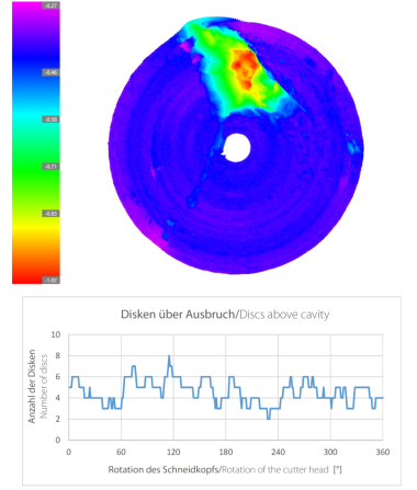
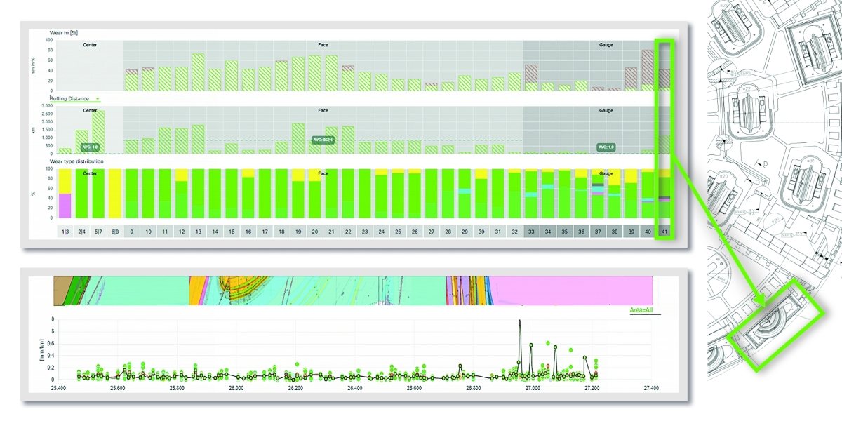 12 | Disc cutter life cycle of Herrenknecht Tools.on software
Credit/Quelle: Herrenknecht AG
A specific use case for a predictive service is monitoring the condition of the cutting tools (Fig. 12), combined with a tool change prediction in conjunction with the actual ground conditions. The aim is to create an early prediction for necessary tool changes based on current and past tunnelling conditions and dynamically adjust it with the drive length. This not only gives a tunnelling project planning certainty with regard to downtime planning for disc cutter changes. Based on the recorded consumption, it is also possible to calculate how many disc cutters will be required during the course of the project and whether existing stocks will be sufficient at all times. In addition, such tools enable an in-depth evaluation of the performance of the disc cutters based on key performance indicators. This helps identify the most suitable tool based on solid data, which in turn has an impact on the initial prediction.
Application Scenario: Reconditioning and Reuse
The reuse of reconditioned TBM assemblies and components or entire TBMs has a major impact on reducing the equipment‘s carbon footprint. The availability of the operating data and maintenance history of a TBM or its subassemblies is key information to assess the remaining service life and/or the required steps of remanufacturing or refurbishment.
4 Outlook
In light of the above, a more general assessment of the situation can be outlined as follows: jobs in mechanized tunnelling are becoming increasingly safer and more attractive; jobsites are achieving ever greater efficiency; the machines used are equipped to cope safely with ever more demanding conditions; overall, there are clear trends toward the idea of sustainability being effectively adopted by all stakeholders and in all processes – looking at the progress that has already been made and the progress that can be expected in the coming years is encouraging.
The disciplines that are currently providing the main impetus for this progress are digitalization and automation. The topics only briefly touched on above are examples of practical implementations of the concept of a largely automated and extensively digitalized tunnelling system. The use of the subsystems mentioned above on specific tunnelling projects is proving successful. With the jobsite experience gained from these systems and the resulting subsequent development steps, further improvements toward safer and more efficient operation and, not least, more attractive jobs will be achieved.