Västlänken, Lot E05 Korsvägen – Inner-City Tunnelling in Complex Hydrogeology
In 2021 the Västlänken project (West Link), a railway tunnel underneath the city centre of Gothenburg, has been presented in tunnel-issue 06/2021. The publication gave an insight into the project’s tendering phase and chosen partnership collaboration approach. Also the different tunnelling methods, which are required at “E05 Korsvägen” to cope with the heterogeneous ground conditions, were presented. Three years later, several sections of the tunnel structure have been handed over for fitting out and track laying, while other parts of the tunnel are in full production process. This article gives an update on the project status and focuses on selected technical solutions, such as concrete columns supporting large rock caverns and one of the first NATM-drives in Sweden (NATM = New Austrian Tunnelling Method).
Credit/Quelle: West Link Contractors
1 Introduction
In addition to its central location between Scandinavia‘s major cities of Copenhagen, Oslo and Stockholm, the city of Gothenburg is the main economic hub in western Sweden. To accommodate the city‘s prosperous growth, the Västlänken project will increase the capacity of the local and commuter rail network.The project currently under construction is scheduled to be fully operational between 2030 and 2032. The joint venture West Link Contractors (WLC), consisting of NCC Sverige AB and Wayss & Freytag Ingenieurbau AG, was awarded the contract for the E05 Korsvägen section by the Swedish Transport Administration (Trafikverket).
2 Boundary Conditions: Inner-City Location and Hydrogeology
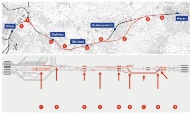
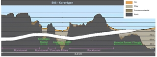 1 | Sectioning of lot E05 Korsvägen project, determined by geology and geography
Credit/Quelle: West Link Contractors
The West Link project and especially the lot E05 Korsvägen is characterized by its heterogeneous hydrogeology. Created during the ice age, very soft to quick clays, glaciofluvial moraine and very compact bed rock dominate the Scandinavian geology. Within the 8 km long alignment of the West Link the bedrock horizon varies significantly, leading to sectioning of the entire project not only geographically but also influenced by the geology (Fig. 1). On the 3.2 km long stretch of the E05 Korsvägen project there are multiple sections in rock, where the tunnel is driven by the conventional drill & blast method. In three sections the rock horizon descends, creating valleys filled with soil. These three sections – Korsvägen, Liseberg and Almedal – are executed using cut-and-cover tunnelling. The found stratigraphy of the soil consisting of very soft to quick clays and an underlaying friction layer ranging from fine and compact silty sands up to coarse glacial gravels with boulders of a size of more than 3 m brings special challenges for the retaining structures of the open excavation boxes. Depending on the inclination of the rock horizon, the thickness of the overlaying ice shield ten thousands of years ago and the streams during the melting the thickness of the moraine varies from 0–20 m. The overlaying clay ranges in thickness from a few meters up to 25 m within the Korsvägen project and shows partly thixotropic properties tending to soil liquification, if disturbed.
The hydrology within the project is characterized by two groundwater aquifers. The upper aquifer is located in the fillings close to the surface. The lower aquifer is confined and streams between clay and top rock within the layer of frictional material. As the lower aquifer streams in South-North-direction the design of the crossing areas of the open excavations in Korsvägen and Liseberg running in West-East-direction require special attention to prevent damming or even a complete cut of the stream. Due to the sensitivity of the soft clay even minor changes in the hydrology can lead to significant soil displacements in hundreds of meters outside of the construction sites area.
The soft soils and its interface to the very hard rock together with the hydrology and the inner-city location of the Västlänken-tunnel result in very low deformation and vibration limits in the surroundings. In direct vicinity to the Korsvägen station excavation box a science centre with sensitive sea life and birds is situated. Another important stakeholder constitutes the Liseberg Park, Scandinavia’s largest theme park, that is crossed by the tunnel alignment. To keep the park fully accessible for the public throughout the project duration, with the NATM a method with small settlements is applied. Due to the inner-city location several utilities and traffic ways, such as tram lines, roads, and railway corridors must be maintained, requiring robust design solutions in connection with extensive monitoring systems.
3 Construction Pit – Korsvägen Station Mid
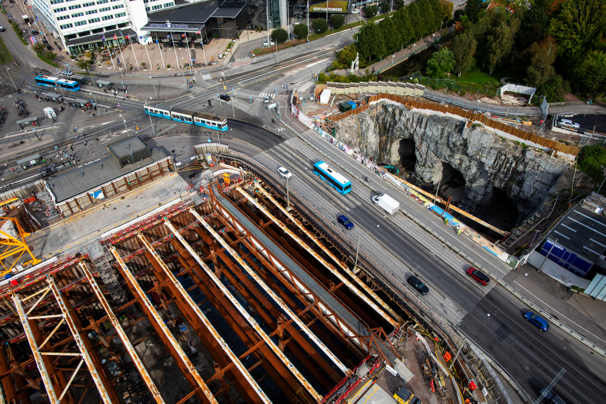
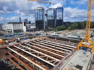 2 | View of the Korsvägen station excavation pit
Credit/Quelle: West Link Contractors
 3 Cross section of the Korsvägen station pit
Credit/Quelle: West Link Contractors
 4 | Example view of rock/retaining wall interface, north wall – west part
Credit/Quelle: West Link Contractors
The Korsvägen Station forms the heart of the Korsvägen lot. The new station’s location at a major traffic junction, which is to be kept operational throughout the project period is one of the major challenges. Therefore, the original concept to divide the pit into two phases with traffic relocation is optimized to the so called “Onebox”-solution with a temporary traffic bridge over the pit. This adjustment benefits the excavation sequence as well as construction of the entire station in one go.
Fig. 2 shows the construction pit for the 140 m long and 55 m wide mid part of the station in its final excavation stage. The approximately 21 m deep excavation in the central part of the valley is supported by RD pile and secant pile walls. At both sides of the valley, open rock excavations with rock bolts were made below the retaining walls and around the rock tunnel portals.
The retaining walls consist of ø1.2 m secant bored pile walls with two layers of reinforcement in the eastern part and ø0.8 m RD pile walls in the western part. In addition to the rock embedment, they were supported by up to four layers of prestressed up to ø1.4m steel pipe struts. Due to the large span of 55 m, the struts were designed with intermediate supports by two rows of RD steel columns, combined with cross beams, plan bracings and diagonal elements to form a 3D bracing system (Fig. 3).
Especially the RD pile installation method according to [1] provided a high and reliable production rate when drilling into the rock or through boulders of approximately 5 cm/min. Overall, a very high installation accuracy could be achieved such that two interlocked closing sections could be produced where the closing piles were provided with adapted RF-locks. The RD piles are associated with a relatively high material cost, but for the site-specific conditions, the RD pile method was very reliable and provided high quality.
The rock excavations for the station were made as 1(H):9(V) open cuts reinforced with rock bolts. The rock was used as toe support by embedment of the piles into the rock. Where the rock surface was above the final excavation, a 1.5 m wide rock bench was made in front of the wall piles and used to install toe anchors. The use of RD piles in the western part allowed to re-establish the natural groundwater flow in the valley in the permanent situation by cutting the piles (with temporary soil freezing for watertightness) and installing steel groundwater pipes in the base slab of the station.
The rock mass is the most challenging geological layer and makes construction pit solutions in this region unique. Gneiss was found in a wide range of strength and very different degrees of weathering and fractures. For the execution of the retaining structures the following features created the biggest challenges (Fig. 4):
very alternating/partly very steep rock surfaces which were difficult to define in pre-investigations but also during the installation of the retaining walls
fractures/fault zones with very low rock strength and high-water conductivity
very weathered rock at the top made the rock curtain grouting but also the installation of the toe anchors a challenge.
The dense pattern of soil-rock soundings provided overall reliable results with respect to the rock surface. However, in areas with steeply dipping rock faces transverse to the retaining walls the surveyed rock levels after excavation showed partly deviations of up to 3 m. But under consideration of all available information, the decisions were always taken on the safe side – meaning the piles were installed sufficiently deep.
The production process was further affected by several fault zones where the rock was of much lower strength and very permeable. In these areas extensive rock curtain grouting had to be executed. The target value of K<10-8 m/s in follow up water loss tests could not be fulfilled in all test sections.
The rock quality has a vital impact on the structural behaviour of the retaining walls. According to monitoring results and later post-calculations, the rock provided more restraint of the retaining wall and, hence, also smaller overall strut forces than assumed in the design. Further research on this may allow further optimization of retaining structures under such conditions.
Regarding the watertightness of the pit very high requirements had to be fulfilled. The thin layered and water bearing sediments and fractured rock are highly confined by thick deposits of soft marine clay. Any drawdown results in accelerated settlements and may affect wooden pile foundations, therefore the surrounding groundwater levels are not allowed to pass below natural levels. This was achieved by the secant pile and RD pile walls providing a high degree of water tightness. Furthermore, to limit the inflow through the rock excavation faces and the bottom of the pit, rock curtain grouting with micro fine cement was designed and executed to 10 to 15 m depth below final excavation level all around the construction pit. Over the length of the retaining walls, the grouting was executed through injection tubes in the piles. Finally, 22 infiltration wells were installed around the construction pit (11 active wells).
In general, the concept of building a highly watertight construction pit and infiltrating groundwater outside the pit has proven successful and fulfilled the contract requirements. With the final excavation levels reached the construction pit had an average inflow of 29 l/min.
This equals 0.12 l/s/1000 m² and is about 10 % of the usually defined reference value of 1.5 l/s/1000 m² for a watertight construction pit [2]. The infiltration scheme worked well to maintain the contractually required groundwater levels.
4 Rock and Concrete Columns Between Korsvägen and Liseberg
How to support 50 m wide tunnel cross-sections underneath low rock cover with poor rock quality? The solution for the tunnelling sections in rock adjacent to the Korsvägen station excavation box seems close at hand, by constructing 17 mega columns along the 140 m underground station length, composed of heavily reinforced C60/75 self-compacting concrete.
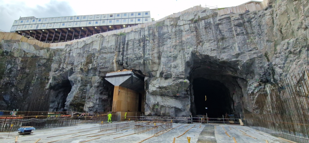 5 | Concrete Columns Korsvägen-West
Credit/Quelle: West Link Contractors
Initially, three parallel pilot tunnels were excavated by drill and blast technique. The remaining rock pillars between the pilot tunnels support the 50 m span during the construction phase of the concrete columns in the centre pilot tunnel, as seen in Figure 5. During the sequential excavation of the solid rock pillars – adjacent to the concrete columns – the load redistribution within the expanded tunnel geometry is closely monitored remotely by multiple sensors built into the concrete columns. The mega columns contain a total of 1300 tons of reinforcement, with an average reinforcement ratio of 370 kg/m³, reaching up to 600 kg/m³. The total concrete volume amounts to approx. 3500 m³. Despite not having the highest numerical values, the project’s planning, unique design, and complex interfaces present significant execution challenges in engineering & craftmanship. Immense rock forces made several design iterations necessary. Reference projects with concrete columns in partially fractured, hard, shallow rock were scarce. The load transfer from rock to concrete column is complex and cannot be assessed as a continuous process as with soft rock.
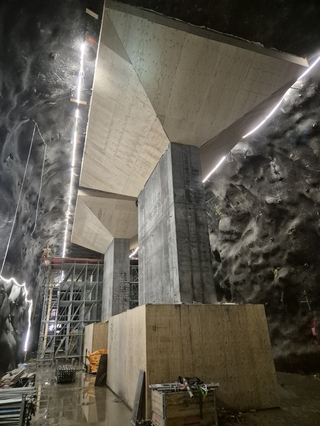 6 | Foundation, Pillar and Capital
Credit/Quelle: West Link Contractors
 7 | Capital reinforcement with cooling pipes
Credit/Quelle: West Link Contractors
Despite these challenges, execution proceeded, and continuous optimization in design and close collaboration during the production phase led to a successful realization. Each column has the following three main elements, as shown in Figure 6: foundation, pillar, and capital/beam. Reinforcement was executed at an average rate of 20 hours per ton, with varying complexity and duration for the individual elements in a confined underground environment. Self-compacting C60/75 concrete was pumped into a closed formwork and against a deviating sprayed concrete surface, necessitating the installation of pressure cells, avoiding hollow voids. Small sensors, coated in silicon, were placed in the deepest surface deviations to detect pressure once the concrete was pushed towards the sprayed concrete tunnel arch. Several individual casting sequences were analysed by the production team beforehand to determine the best suited concrete casting approach, which was then tested on a 1:1 mock-up. Continues amendments during production optimised its buildability regarding the installation of heavy reinforcement cages and concrete castings. Due to the high content of “anläggningscement” consisting of fly ash and limestone, the concrete bonded quickly. Cooling the concrete element was mandatory to prevent hydration temperatures from exceeding 70°C (Fig. 7). Slump tests, ranging from 650 to 720 mm, were conducted for each concrete truck delivery to ensure the concrete maintained the required flowability into the highly dense reinforcement cages.
The concrete columns have been completed in the Eastern Station part of the project. Currently, the close-by rock elements are being blasted away, introducing yet another challenging interface. With the successive removal of the adjacent rock pillars the concrete pillars are loaded by the activated arching effect in the rock mass above. This phase involves the mentioned monitoring system, including fibreoptic sensors, tape extensometers, and load-measuring systems, which is also implemented for the duration of the 120-year design life of the railway project.
5 NATM-Drive Under Liseberg Amusement Park
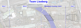 8 | Overview Construction Section Liseberg
Credit/Quelle: West Link Contractors
 9 | Tunnel profile and longitudinal section incl. stratigraphy elevations of clay (green), friction material (yellow) and bedrock (red)
Credit/Quelle: West Link Contractors
As mentioned in the previous article in 2021 the construction method of construction section Liseberg West 1 in the area Liseberg was changed during the production phase due to various reasons. One reason with a big impact was definitely the production and working times which are dependent on the opening times of the Liseberg amusement park. The Liseberg park is one of the biggest of its kind in the Nordics and highly frequented. The whole construction pit is surrounded by the Liseberg Park as it can be seen in Figure 8. It starts in the West 1 area, crossing the main entrance of the amusement park. Subsection West 2 is just built next to Rondo, a historical venue hosting shows. Furthermore a sport hall had to be removed as well as a restaurant before even starting with special foundation works. Going towards east, the Liseberg section is crossing river Mölndalsån. To keep the river in it’s original shape, an aqueduct is installed temporarily to build the pit and the concrete tunnel underneath the running river. Before the open pit excavation section turns into a drill & blast section towards east, the pit East 2 has to be excavated right in front of the European highway E6 and the existing train tunnel “Gårdatunnel”.
With the focus on the subproject Liseberg West 1, which can be seen on the left side in Figure 8, the whole construction pit is located in the main entrance of the Lisebergpark. Keeping the impact on third parties and specifically on the visitors low was always one of the most important goals which the project E05 Korsvägen is aiming for. Therefore, it was only possible to have building activities above ground within this area during a short period each year of around 12 weeks when there is a winter break in the amusement park. This approach would have caused a quite unstable production utilization. Taking all the boundaries into consideration the JV West Link Contractors decided to change the production method in Liseberg West 1 from an open pit construction to an underground solution.
Originally it was planned to install secant bored piles, excavate the soil and blast the remaining rock from above as a regular open excavation box. Approximately 50 % of the tunnel itself is located in hard rock and around 50 % in soft clay, moraine and sand as you can see in Figure 9. With the given ground conditions in Liseberg West 1 it was not possible to use the in Sweden very well-known drill & blast method. Therefore, a sprayed concrete lining concept was established by using initial approaches from the New Austrian Tunnelling Method (NATM). Using a technique that isn’t widely practiced in Sweden presents its own set of challenges. One of the keys for the successful tunnel drive was to have an experienced designer on board to be able to get a design approved which on one hand adapted the local standards and preferences but on the other hand respects the ground principles of soft soil tunnelling. In this case the Austrian engineering office Laabmayr & Partner worked out a solid design based on a sidewall tunnel drift. Figure 9 illustrates the excavation scheme made out of six excavation parts.
The left side of Figure 9 shows the tunnel profile with a total excavation area of 244 m²; on the right side the geological longitudinal section can be seen. Proceeding with the tunnel drive from tunnel meter (TM) 00,00 to TM 26,20, it can be observed, that the first 5 m of the tunnel drive are characterized by full-face hard rock. After the first meters the rock horizon descends in the direction of the tunnel drive. In the last advance the whole tunnel profile is dominated by soft clay. That means in only 26,2 m of tunnel, a quite big range of geological conditions can be found. Furthermore, sand lenses filled with water were expected as well as the groundwater table close to surface.
The tunnel drive itself was already surrounded by secant bored piles from the original plan to have an open excavation pit and D-wall panels towards the construction pit West 2. Additionally jet grouting columns were installed between the rock horizon and the secant bored piles/
D-wall to seal the tunnel drive area. Therefore, the water table in construction section West 1 was drained from surface in advance using ejector wells. The remaining water in the ground, surface water and leakages were handled during the tunnel drive with relief wells and drainage pipes.
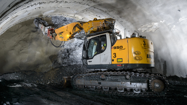
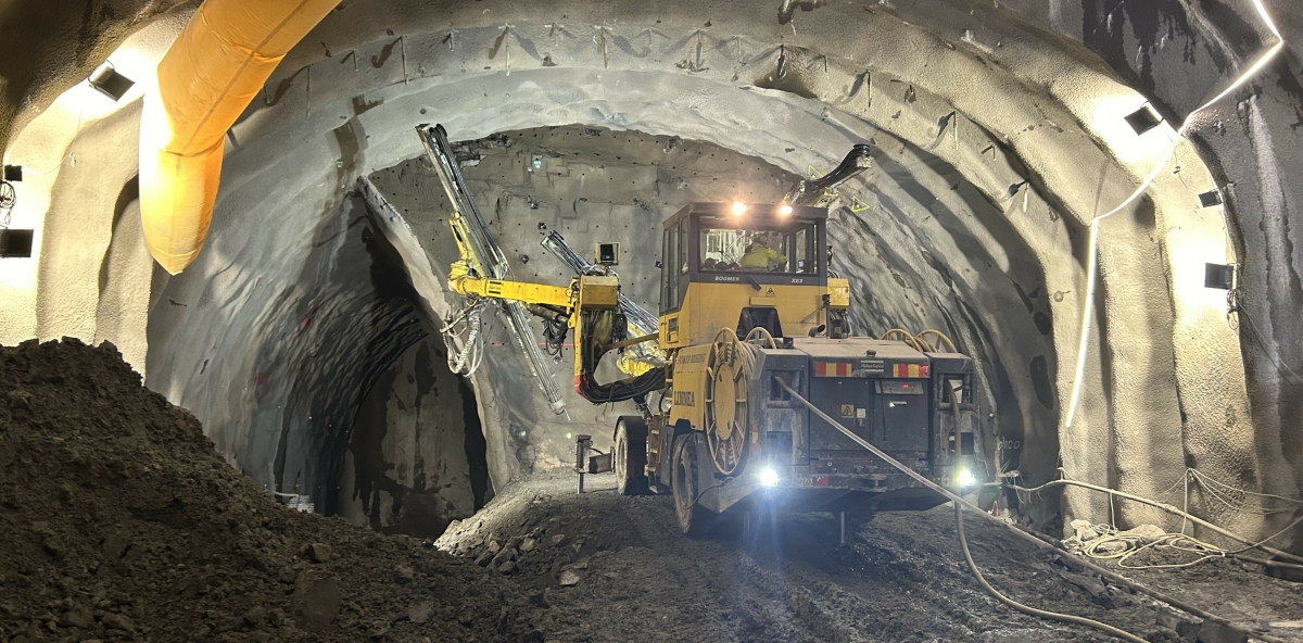 10 | Drilling for blasting in excavation area 3a
Credit/Quelle: West Link Contractors
Figure 10 shows the drilling rig preparing the blasting holes in excavation area 3a. At this stage the tunnel face in 3a was completely in hard rock. At this stage of the tunnelling cycle, it was particularly challenging to manage the reactions of sensitive animals, such as sharks and birds, to the blasting vibrations and airborne noise. These animals were housed at Universeum, a public science centre located approximately 100 meters from the tunnel face. Since the tunnel drive started in pure hard rock but the rock horizon is falling steep, the reinforcement effort was high from the beginning with a 40 cm sprayed concrete shell to provide a evenly stiff support structure reducing the vibration impact on the surroundings.
The tunnel drive for the construction Liseberg West 1 started in December 2023 and has been finished in May 2024. During 2024 the inner lining will be installed. As a result, the goal of keeping the impacts on surroundings low, has been achieved without big dependencies on Liseberg Park’s opening times.
6 Outlook of the Project
While in the Almedal area the concrete tunnel and trough is scheduled to be finalized by end 2024 while track slab and installation works are taking over, the concrete works for Korsvägen station are fully ongoing. In the rock tunnels as well as in Liseberg area excavation works are planned to be ongoing until 2027, while the underwater excavation underneath the river Mölndalsån and the top-down excavation in Liseberg West 2 served through the NATM-tunnel represent special technical and logistical challenges.

