New Ground Support gains Traction in China
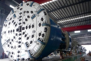
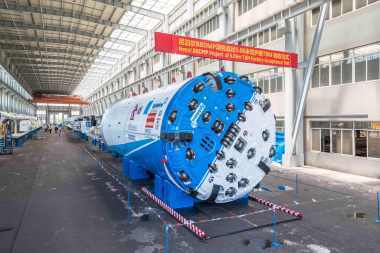
More than eight hours away from the nearest city sits China’s Qinling Mountain, part of a range soaring up to 3,767 m high. About halfway up the mountainside is the jobsite for the Qinling Rail Tunnels, currently being excavated beneath 1,400 m of rock. Two 10.2 m diameter Robbins Main Beam TBM were launched without roof shield fingers, and with ground support tailored to the specific conditions. “New types of ground support are becoming more accepted in China. Methods such as the McNally Support System are in the trial stages, while customized programs using wire mesh, ring beams, and rock bolts are being adapted for most hard rock tunnels,” said Biyue Li, Robbins Vice President-Far East Operations.
Several Chinese projects, including the Jinping-II Hydroelectric Project beneath 1,500 m of cover, are taking cues from experiences at other deep bore tunnels, such as the Gotthard Base Tunnel and Olmos Trans-Andean Tunnel. The resulting systems based on these experiences are standing up under the pressure of squeezing ground, rock bursting, rock falls, and other common obstacles.
Jinping-II Hydroelectric Project
China’s Jinping-II Project will be the largest power station in an ambitious 21-station project for owner Ertan Hydropower Development Co. Ltd. The project will harness up to 25 mio. MW per year from the Yalong River for China’s West to East Electricity Transmission Project. Power from these stations and other resources in the west will be transmitted to Guangdong, Jiangsu, and Zhejiang Provinces, as well as the cities of Shanghai, Beijing, Tianjin, and other eastern locations in short supply. The entire scheme is envisaged to go online in 2030.
The Jinping-II site is unique in that it will utilize a natural 180 degree bend in the Yalong River, a tributary of the Yangtze, to generate 4800 MW annually. Four headrace tunnels will travel at a 3.65 % downgrade from intake structures near Jingfeng Bridge to the underground Dashuigou powerhouse, which will utilize eight hydraulic turbine generators. The parallel headrace tunnels, each 16.7 km in length, are separated by 60 m from centerline to centerline. Two access tunnels and a drainage tunnel run parallel to the headrace tunnels on the southern side.
The owner, Ertan Hydropower Development Co. Ltd, chose two 12.4 m TBM, one Robbins Main Beam Machine (headrace tunnel no. 1), and one Herrenknecht machine (headrace tunnel no. 3). The tunnelling and D&B work are split into two contracts–China Railway 18th Bureau (Group) Co Ltd. is responsible for headrace tunnel nos. 1 and 2, while China Railway 13th Bureau (Group) Co Ltd. are constructing headrace tunnel nos. 3 and 4. An additional 15.3 km long dewatering tunnel is being excavated by a 7.2 m diameter Robbins TBM for the contractor Beijing Vibroflotation Engineering Company (BVEC).
Preliminary Geology
Geologic tests showed all four tunnels located in massive, blocky marble with limestone and sandstone between 50 and 85 MPa UCS. A high overburden, with over 70 % of the cover above 1,500 m and a maximum of 2,525 m, creates risk of rock bursting, however. In addition, preliminary core tests showed several faults and fractures, as well as karst patterns with water bursts at a pressure of up to 2.4 MPa in some sections. These same core tests revealed maximum water flows of up to
5 m3/sec, with steady flows of 2 to 3 m3/sec. “These tunnels are under very high stress and high cover at a large diameter. This is a significant and challenging project for the Chinese tunnelling industry,” said a senior engineer working for Ertan.
Robbins specially designed the 12.4 m TBM for high water inflows and difficult ground conditions. The entire TBM, back-up, and continuous conveyor setup in the tunnel were raised 1.5 m above the invert on a continuously installed steel framework, allowing the expected large water inflow to pass under the back-up. A ground support program of rock bolts, ring beams, and steel fiber-reinforced shotcrete was also adopted.
Tunnel Excavation
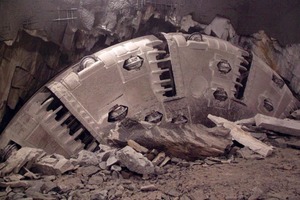
The 12.43 m diameter TBM was launched in late October 2008. During the commissioning bore, increased ground support was required at the interface between the starting chamber and the bored tunnel. The resulting design included ring beam installation every 900 mm and a 17-bolt pattern of rock bolts every 1.5 m. Progress was slow from the outset due to very poor rock conditions. During consecutive months, the bored tunnel continued to experience severe fractures, rock bursting, and collapses.
Engineers opted to design a new ground support system for the TBM in 2009, given that the geology encountered was much worse than originally expected. Through several site visits and meetings with the customer, Robbins developed a total modification plan to cope with the reality of geological problems. According to this concept, steps were taken to rebuild the ground support system inside a modification chamber excavated by drill and blast ahead of the machine.
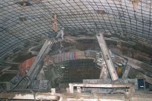
The crew removed key pieces of equipment from the TBM that had failed in the difficult ground conditions. These included the ring beam erector, mesh panel erector, roof shield fingers, work platforms, and materials delivery system. The machine was then installed with a newly designed ring beam erector, a separate roof and probe drill, strategically placed working platforms, and a streamlined invert cleaning system with chain conveyor for removing broken material from the invert. The roof shield fingers were replaced with a curved assembly of pockets for McNally System ground support. The system, designed to prevent and minimize the number of rock falls, has had success at several tunnels including Peru’s Olmos Trans-Andean tunnel. What the McNally system offers is far superior protection for the workers working in the ring building and ground support area. The steel slats provide protection from falling debris against the traditional finger system used on previous TBM. It also keeps the loose rock suspended above the tunnel, reducing the need and expense to fill the cavity with grout or cement by injection.
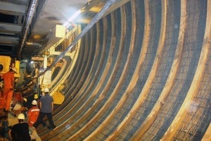
The McNally Support System, supplied by C&M McNally Engineering of Toronto, Ontario, Canada, works by replacing the curved finger shield plate for a curved assembly of pockets with rectangular cross-sections. The pockets extend axially from the rear side of the cutterhead to the cutterhead support, within the area where roof drills can work. Before a TBM stroke, crews slide slats of metal or wood into the pockets, such that the slats are two rows deep inside each pocket. The ends of the slats protrude from the pockets and are bolted to the roof of the tunnel using a steel strap. As the machine advances, the slats are extruded from the pockets and continuously bolted to the roof using subsequent straps. Slats are reloaded and used for the length of the tunnel to prevent deformation and rock falls.
Since installation of the new system, conditions have improved markedly. The McNally support system is not in full use by the contractor yet, but systematic mesh panel installation has contained large blocks of rock. As the machine moves forward, panels of wire mesh are pulled back through the annulus and bolted in place. As of October 2010, the machine was boring in 130 MPa marble, and advancing around 3 m/h, with a best week of 128 m. “We continue to experience rock bursting events at least 500 mm deep, which can damage the cutters and bucket lips when they occur in front of the cutterhead,” said Tom Carlin, Robbins Field Service Superintendent. Behind the cutterhead, bursting events are being supported with wire mesh and rock bolts on the sides and along the top of the tunnel every 1.0 to 1.5 m.
West Qinling Rail Tunnels
The West Qinling tunnels are part of the Chinese Government’s Lanzhou to Chongqing Railway, a massive 820 km long scheme that will link the capital of Gansu Province (Lanzhou) with southwestern Chongqing, a mega-city of over 35 mio. people. The new railway, at a cost of 11.3 billion USD, will shorten transport times from 17.5 to 6.5 hours and enable an annual freight capacity of 100 mio. m3. Trains will run on the double track lines at 160 km/h, with a 50-train daily maximum. The entire railway is expected to open to traffic in 2014.
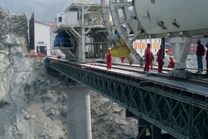
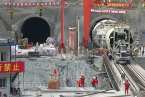
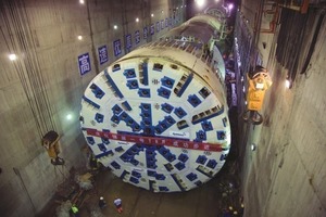
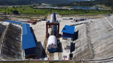
Two 10.2 m diameter Robbins Main Beam TBM are excavating 16.6 km long tunnels from parallel launch chambers just 40 m apart, with their back-up and muck haulage systems starting from bridges across a deep valley. The jobsites are located on the lower reaches of Qinling Mountain, about 1,000 m above sea level. Geotechnical investigations indicate ground consisting of limestone and phyllite, some siliceous phyllite, and fault zones in breccias and clay. Rock strengths range from 30 to 100 MPa UCS. Broken, fractured rock is expected in a 915 m wide section of tunnel, with three large faults specifically identified. The faults, ranging in width from 190 to 310 m in width, consist of fragmented limestone and sandstone with gravels and breccias. Some ground water and karstic features are also expected during the tunnel drives.
In the area of West Qinling Tunnels chronic rains cause the roads to wash out – the current route is a 16 to 20 hour drive through the Xinling Mountains from Chengdu using a four-wheel drive vehicle. At the site, workers live in two camps: one for the right line and one for the left line tunnels. Spare parts and other supplies must be trucked in over several days from either Chengdu or Shanghai.
Novel Ground Support
The machines were designed for high cover tunnelling (up to 1,400 m) in relatively weak rock strengths. The two TBM were the first recent Robbins Main Beam machines assembled without roof shield fingers. Ground support systems include modified mesh installation, ring beam installation, work platforms, and materials handling. During tunnelling, ground support consists of continuous mesh and rock bolts, with either ring beams or steel straps, for the length of the tunnel. In addition the contractor opted to install a 300 mm thick continuous concrete lining for the length of each tunnel.
Safer Mesh Installation
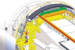
Mesh windows, installed in the roof shield, allow workers to slide panels of mesh in the annular space between the shield and the tunnel crown from the safety of the shield structure. The panels are then pinned or secured with rock bolts. Traditional ground support includes no specific provisions
for mesh installation and little cover from falling rock.
Streamlined Ring Beam
Installation
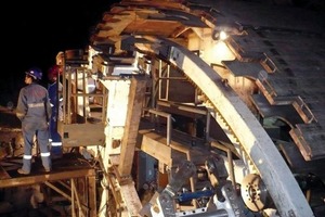
Ring beams are installed using an erector consisting of the assembly ring and expander. The rotating assembly ring is fixed axially and used to loosely assemble five ring beam components. Once the components are loosely assembled and pinned to the assembly ring, the expander, which moves fore and aft, expands the components to a preset pressure against the tunnel wall. A sixth Dutchman piece is installed in the resulting space, and the ring beam with tightened connections is bolted to the tunnel wall. The assembly and expander can also be easily converted for installation of steel straps, rather than full rings.
Previous assembly methods required that the fully assembled ring beam be transported to a pocket before being expanded against the tunnel wall. The method is not as fast, and does not give the flexibility often needed in changing ground that may require steel straps.
A Variety of Work Platforms
Accessible work platforms are located throughout the machine, including two in front of the ring beam erector and under the roof shield for mesh installation. Other work platforms are located at various levels around the circumference of the machine for ring beam and rock bolt installation.
Efficient Materials Handling
Streamlined materials handling allows the ring beam components to be transported efficiently to the L1 area. The system reduces the number of transfer points, and ultimately reduces the number of crew members required to transport materials.
Ground support components are loaded onto the back-up using a crane, and placed onto a carriage riding on an electric transport car. The carriage is designed to hold a stack of mesh panels, ring beams, rock bolts, and lagging materials for the McNally system. The remotely operated trolley carriage transports the materials to a rack located in front of the ring beam guide rollers where they can be easily placed.
Increased Range of Motion for Drills
Instead of a combination roof and probe drill, the setup utilizes separate roof and probe drill canopies. The system allows a wider range of motion and better access from nearby work platforms.
Optional McNally Ground Support
If more difficult ground is encountered, the mesh pockets can be relatively easily converted to use a modified form of the McNally System. Crews would bolt McNally pockets inside the mesh pocket structures, allowing a space to slide short slats of steel or wood into the area where roof drills can operate.
Current Tunnel Excavation
The machines were launched in June and July 2010. As of October, the TBM were excavating at good production rates of up to 595 m/month. Ground conditions have varied, but the majority have required full ring beams every 180 to 900 mm, depending on the severity. Cover was still relatively low, approx. 250 to 300 m. Both tunnels had just commenced lining works, which consist of the installation of a waterproofing membrane to the tunnel walls, followed by a 120 m long concrete pour.
The Modified Ground Support
High cover tunnels are host to a range of problems from squeezing ground to falling rock. In cases of severely unstable ground, tunnelling is hindered by structures such as the finger shield. The structures allow the rock to fall several mm before they are stopped, creating substantial problems with bolting back the falling rock.
“I am certainly a proponent of the McNally system. The system can be easily modified to comprise different capacity support components, making it ideal for varying rock conditions. In shallow tunnels with horizontal geology, for example, the system can comprise relatively low capacity support components that are easy to install. For deep tunnels where high stress conditions exist with possible rock bursting, the system can be enhanced with high capacity, larger components that can still be practically installed with TBM excavation,” said Dean Brox, Senior Project Manager – Tunnels for consultant Hatch Mott MacDonald.
Other options include combinations of ground support. “In better ground, steel channel support installed over the tunnel roof section in conjunction with mesh and patterned rock bolts is a good option. This support design is installed immediately behind the cutterhead and within the fingershield and provides an appropriate support to stabilize the tunnel and protect workers,” said Brox.
Ideally, a long tunnel in variable ground will have some options for conversion depending on the ground conditions. The good excavation rates on China’s deep bore projects are proving the systems viable options for today’s difficult high cover tunnelling.

