Fire Protection for Bjørvika Underwater Tunnel in Oslo
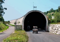
For constructing the Bjørvika Underwater Tunnel in Oslo/Norway (Fig. 1) extremely high demands are placed on fire protection. The following report presents them in brief.
The engineers responsible for the tunnel structures largely rely on regulations governing the design of buildings namely European legislation. The temperature within the concrete is calculated, which provides the bearing capacity (Figs. 2 + 3). These calculations are suitable for a large number of applications although they reveal limitations. According to Standard EN 1992-1-2, which incorporates the European laws governing concrete structures, the material models are only suitable for heating rates ranging from 2°C/min to 50°C/min because the creep deformation effects are not explicitly taken into consideration. The Norwegian authorities held the view that this leads to false conclusions. They preferred to choose models for tunnel linings, which are aligned to a faster heating rate and correspond to the Dutch RWS standard fire curve, for which the maximum rates of heating amount to between 200–240°C/min.
Impacts caused by Heat Expansion in statically non-determined Structures
In order to establish suitable fire protection linings the Swedish and Norwegian authorities carried out a series of fire tests on heavy concrete with 3 different products in the course of 2006 and arrived at the following outcome: the fire resistance regarding temperature response behaviour and spalling was determined for various concrete qualities. Very good results were obtained with polypropylene fibre concrete. However, major issues exist as far as the long-term behaviour of these fibres is concerned especially pertaining to the frost resistance and chloride penetration.
The World’s strictest Fire Test for Tunnels
The tests, which were carried out on concrete with particular protective devices, were not satisfactory, for although the results for applied products were documented, these did not stand up to the extreme strains posed by the test series. In the study in question 3 different systems were tested with a loaded slab with a concrete compressive force of 5.5 MPa, and all failed. As a result the Norwegian authorities published a report in June 2007 (TR-2494), describing the methods applied for testing fire protection systems in tunnels. This is compiled in keeping with the RWS standard fire curve, whereby the flexural moment of the statically non-determined structure is provided as accurately as possible so that the fully plastic moment created by the permanent load resulting from temperature increase can be simulated.
The Highway Authority did not wish to take over the fire test method for bored tunnels executed in the Netherlands as none of the loads, which are applied to statically non-determined structures, are recorded.
The fire tests have to be carried out using large pre-tensioned concrete elements, which possess a span width of 3.6 m and which are placed in a horizontal furnace; the slab is designed to sustain a load of 4,644 kN so that a theoretical compressive strength of 12.9 MPa can be applied at the exposed side (Fig. 4).
The Norwegian authorities did, however, take over the philosophy contained in the French circular 2000-63 Recommenda-tions March 2005, in order to apply the test to large loaded slabs (4 x 3 m) and to subject it to a load.
In view of the cumulative demands with a large effective spread and load given a 300 MW fire it can be maintained that FireBarrier 135 passed the world’s most sophisticated fire test for underwater tunnels and/or statically non-determined structures.
The fire tests have to be carried out in a laboratory with ISO 9001 or ISO/IEC 17025 certification. In addition, it was essential that the material is tested for frost resistance in keeping with EN 1387-1 (40 cycles of –20°C to 10°C) and that a permanent strength test (50 mill. cycles) as well as tests applying to high-pressure cleansing resistance (150 bar), alkali and carbonisation resistance were undertaken.
Performances of the sprayed Mortar
After 15 previous fire tests with FireBarrier 135 at different labs (TNO, CSI, CSTB, SINTEF) taking various standard fire curves (RWS, HCinc, ISO) with various types of concrete (compressive strength varying from 35 to 76 MPa), Innovative Fire Systems and Thermal Ceramics decided to undertake intensive tests for a year on the basis of the requirements set by the Norwegian Highway Authority.
Some tests relating to fire resistance, physical properties and long service life were carried out at the Swedish National Institute for Experiments and Research in Borás. The fire load is devised for a 300 MW fire during a period of at least 2 h (in accordance with the RWS curve). The surfaces were protected with a 36 mm thick FireBarrier 135 layer, which for its part was reinforced with a 50 x 36 mm thick wire grid made of stainless steel, 1.9 mm in diameter and connected every 40 x 40 cm using spacers and anchors. After 2 h the average temperature at the interface amounted to less than 265°C.
The alkali resistance was tested in accordance with Norwegian specifications. The sample for fire resistance has to set/be prepared at least 6 weeks prior to the start of the test at 23 ± 2°C (50 ± 5 % RF). A sample series (at least 5 samples to be examined) was placed in 1N NaOH (sodium hydroxide) for 2 days at 23 ± 2°C, rinsed with distilled water and prepared at 23 ± 2 °C (50 + 5 % RF) for at least 4 weeks. Parallel to this another test series (at least 5 samples to be examined) was prepared for at least 4 weeks without prior alkali effect at 23 ± 2°C (50 ± 5 % RF).
Subsequently the adhesive tensile strength for both series was tested in accordance with EN 1542:1999. The adhesive tensile strength of the fire protection regarding the reference concrete was not reduced by more than 20% on account of the effect of alkali and the lining did not display any damage at all owing to the effect.
The carbonisation resistance test was executed in accordance with EN 13295:2004, carbonisation resistance owing to a CO2 reaction resulting from the traffic volume. The frost resistance test was for its part carried out in keeping with EN 13687:2002. The test is concluded following fifty 4-hour cycles. The test consists of submerging the concrete for 2 h in a tank with a saturated sodium chloride solution at a temperature of –15°C ± 2°C and then stored in a water tank for 2 h at a temperature of 21 ± 2°C.
The permanent strength test was undertaken in accordance with the Norwegian specifications. The fire protection including the mechanical anchors corresponds to the requirements of the traffic loads that the tunnel is exposed to. The tunnel is designed to cope with 100,000 vehicles per day.
The following dynamic forces were applied for 15 mill. cycles with respect to pressure/suction: 1.97Kpa separation/ 1.56 Kpa compression.
The high-pressure cleansing test was also undertaken according to the Norwegian specifications. The fire protection system and its surfaces must withstand normal tunnel cleansing procedures at periodic intervals: 120 cleansing procedures at 50–150 bar were executed 1 min long per m² with water pressure ranging from 10 to 25 l/min/nozzle from a distance of 500 mm between the nozzles and the fire protection system in order to simulate the total anticipated service life.
Application of the sprayed Mortar
In the case of the Bjørvika Tunnel more than 35,000 m² of FireBarrier 135 is to be applied before the start of autumn.
70 workers and technicians are engaged for this purpose. The construction site organisation foresees teams, which are individually responsible for cleansing the base, assembling the grids and the guide rails, for spraying on and smoothing the mortar and assembly of the expansion joints (Fig. 5).
A strict quality assurance plan was established, which included the following checks; attachment points for the grids, tensile tests for the anchors
(100 daN/unit), distance of the carriers for the spacers, reading the mortar thickness as well as mortar samples in order to measure the density, the combustion and the compressive strength. The adhesive tensile strength is controlled on the spot weekly, in other words 4 times more frequently than requested by the client.
Expansion Joints: the weak Points given a 300 MW Tunnel Fire
The contact points of the flush tunnel segments comprise a seal made of natural rubber with extremely high compressive strength, which does not change even given an increase in temperature.
The expansion movements, which are assumed by the developers result in major elasticity for the entire system over a length of 670 m in the underwater sector.
The expansion joints were at the centre of a joint investigation by Statens Vegvesen and Innovative Fire Systems with the objective of finding solutions for the overall joint problem complex in underwater tunnels:
– an efficient rubber seal (waterstop) does not withstand a temperature in excess of 80°C given exposure to fire according to the RWS curve
– the assumed maximum expansion movement amounts to 3.5 cm in the centre of the tunnel
- high-pressure cleansing (150 bar given a 50 cm gap) is carried out 2 x yearly.
In order to fulfil these requirements a product solution consisting of prefabricated and sprayed components was developed in collaboration with the client, which withstands permanent exposure at 1,350°C (Fig. 6).

