Tunnel Planning – Rock Mechanical Models (AJRM) vs. Classification
This article examines two approaches to the design of tunnelling: the AJRM (Anisotropic Jointed Rock Model) and classification systems based on rock mass parameters. The AJRM takes into account the anisotropy of the rock mass and is used successfully in tunneling, as well as other fields. On the other hand, there are classification systems such as the Q-System, RMR and RMi, which are especially prevalent in Scandinavia and the English-speaking world. However, in the opinion of the authors, the application of these classification systems in sedimentary rocks is associated with major risks and does not provide sufficient reliability in complex geological conditions. The authors suggest that the AJRM should be further developed instead of these systems.
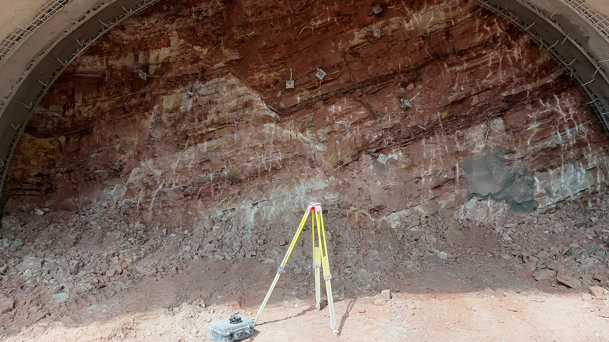
Credit/Quelle: Ingenieurgemeinschaft A44, Bauabschnitt 4.2 und 5
The field of rock mechanics was founded in the 1950s and 1960s. The importance of this new field of Engineering Sciences was already reflected in the founding of the International Society for Rock Mechanics – ISRM for short – in 1962. In §2 of the statutes at the time, the tasks were defined as follows:
a) The scientific investigation of the physical behavior of rock, especially as an inhomogeneous and anisotropic body,
b) The development and evaluation of fundamentals for stability analyses for structures and excavation work in rock as well as for the foundation of structures on rock,
c) The mechanical explanation of tectonic phenomena.
In line with these objectives, research was carried out by Prof. Wittke and his team in conjunction with the institute of Prof. Leussink in Karlsruhe, who was a member of the first board of the ISRM. In this context, Prof. Wittke completed his doctorate and habilitation under Prof. Leussink. Models and calculation methods were developed, which were continuously further developed from 1974 at RWTH and since 1980 at WBI. These model concepts, which have been summarized under the term AJRM (Anisotropic Jointed Rock Model) since 2014, are used very successfully today in tunnel construction, foundation works and slope stabilization.
Parallel to these developments, another method was introduced, particularly in the Scandinavian and Anglo-Saxon countries – the so-called classification systems or prescriptive measures. The Q-system was introduced by Barton et al. in 1974. This was followed by the RMR and RMi systems, which were first published by Bieniawski and Palmström in 1974 and 1995.
These systems are briefly presented and discussed in the article. It is shown that the application in sedimentary rocks is associated with great risks and therefore should not be followed up. Instead, science and research should focus on the further development of the AJRM method, which has been tried and tested over many years. The application of the above-mentioned classification systems in tunnel construction should also continue to be prevented in standardization. We hope that this has been and will continue to be addressed in the revision of EC 7.
The article also discusses the GSI introduced by Hoek and Brown, on the basis of which calculations are possible, but for which isotropic conditions are assumed that do not exist in most cases.
1 Inducement
A critical evaluation of the methods of rock mass classification in tunnel construction was already presented in [1] in 2009. This was discussed in the following years in expert discussions, e.g. in [2], [3] and [4]. Recent experience gained in the course of our project work and the imminent introduction of the new EC 7 have prompted the authors to take up the subject again.
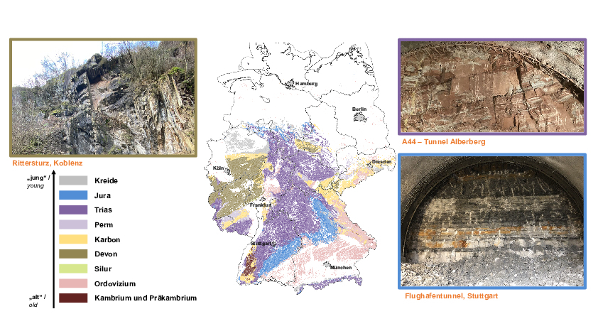 1 | Distribution of Geoligical Units in Germany, overview
Credit/Quelle: WBI GmbH
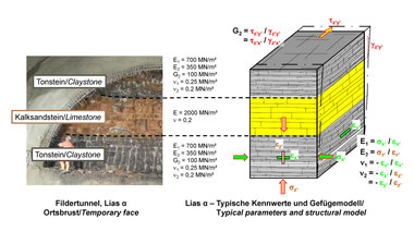
In order to be able to do this properly, the geological and subsoil conditions in which tunnels are to be built must first be considered. Figure 1 shows a geological overview map of Germany as an example. It can be seen that from the middle of Germany to the Alps, mostly solid rock is found near the surface. These are mostly sedimentary rocks with pronounced stratification and jointing. Figure 1 shows examples of Devonian layers (Rittersturz in Koblenz), Bunter (A44, Alberberg tunnel) and Black Jurassic (Stuttgart airport tunnel). These photos show that it is essential to realistically describe the rock mass, including the intact rock and the discontinuities and thus, the anisotropies and inhomogeneities, when planning tunnel structures.
2 Planning on the Basis of Rock Mechanics
In order to advance science in this respect, the ISRM (International Society for Rock Mechanics and Rock Engineering) was founded in 1962 as a result of the Salzburg Circle. The aims of the society (see above) were defined in the first statutes [6]. According to this, the task of rock mechanics is to make the rock calculable in a similar way to concrete in solid construction or soil in soil mechanics.
In line with these objectives, the rock mechanics section of the DGGT was founded in 1969. In 1972, a major symposium was held in Germany at which the fundamentals of seepage flow calculations were presented and discussed. Since 1980, WBI GmbH, under the direction of Prof. Wittke, has been involved in the application and research of rock mechanics. During this period, publications such as [7] and [8] have been published and, since 2015, the annual Rock Mechanics and Tunnelling Day has been held in Weinheim in this context.
The applied research and development of recent decades have made it possible to proceed in accordance with the generally recognized procedure for the planning and execution of tunnel construction projects in rock, according to which rock mechanical models are developed on the basis of geotechnical investigations. These in turn form the basis for the analyses of stability and serviceability and finally the design and planning, taking into account the relevant guidelines and standards. According to the observation method, the structural behavior during construction is checked and compared with the forecasts. This procedure (AJRM method) has now been successfully used by WBI-GmbH for 44 years.
3 Classification Systems
In the Anglo-Saxon world, a different approach was taken. In 1980, Hoek-Brown introduced a failure criterion, which in 1995 was linked to the GSI ([9], [10]). Stability analyses are of course possible with the methods introduced there, Stress-strain behavior of the rock however is greatly simplified and inhomogeneities and anisotropies are neglected. As shown in [17], for example, this often leads to economically inefficient designs.
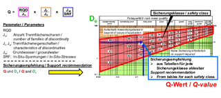 2 | Q-system, evaluation of support recommendations
Credit/Quelle: WBI GmbH
Coming from Scandinavia, the so-called classification systems were introduced (Figs. 2 & 8). The Q system and the RMR system were published for the first time in 1974 and the RMi system by Palmström in 1995 [11], [12], [13].
Using the corresponding rock mass parameters, it is assumed to be possible to determine characteristic mechanical parameters for the rock using empirical formulas. This will not be discussed in detail in this article. However, it should be noted that calculations carried out on this basis have the same disadvantage as the Hoek-Brown methods – they neglect anisotropy and inhomogeneities or make inadmissible, simplifying assumptions in this regard. They therefore also do not meet the objectives of the ISRM.
This article will discuss the design methods introduced on the basis of the above-mentioned rock mass indices, which are often described internationally as prescriptive measures.
Q-System
According to the Q-system, the properties of the rock are described by the so-called Q-value, which results from the product of six constants (Fig. 2). The second input parameter required for the design of a tunnel support is the diameter of a tunnel and the so-called ESR (Excavation Support Ratio), which can be derived from tables for different types of structures. The value De is calculated from the quotient of the diameter and the ESR. De and Q form the input variables for a nomogram from which a so-called safety class can then be derived (Fig. 2). The support to be installed for this safety class can be obtained from tables. Further calculations and safety considerations in terms of standardization are not provided.
Prof. Nick Barton states in [11] that the Q-system can be applied to the entire spectrum of rock qualities. The authors of this paper are convinced that this statement is not tenable for several reasons.
First of all, it should be noted that the nomogram was drawn up in 1974 on the basis of 212 case studies. Only 19 of these tunnel projects were in sedimentary rock. It is obvious that this small number of examples can in no way be sufficient to justify the admissibility of using the system in all rock conditions. This is still true today, even though the nomogram was further developed in the 1990s on the basis of more than 1000 case studies [18]. A closer view shows, that these were also almost exclusively tunnel constructions in crystalline rock.
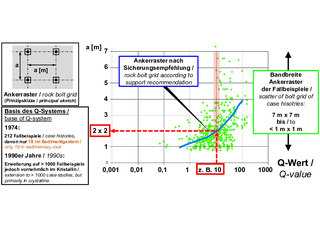 3 | Support recommendations based on case studies [19]
Credit/Quelle: WBI GmbH
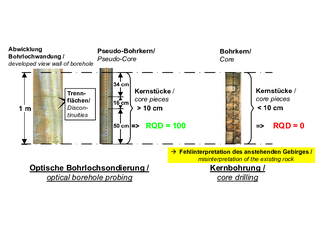 4 | Influence of core quality on the RQD value
Credit/Quelle: WBI GmbH
Nevertheless, the applicability of the method for tunnel structures in crystalline rock also appears questionable. In order to substantiate this statement, Figure 3 shows the anchor grid, which results from the support recommendation of Barton. According to [19], the support recommendation is based on the case examples marked with green dots in Figure 3. There is certainly no correlation between the Q value and the anchor grid, which has been applied in the corresponding case studies.
Even if these explanations alone show that the Q-system does not meet today‘s requirements for tunnel planning, further risks that can arise from the application of the system will be shown below. To this end, the various input variables for determining the Q-value will be examined in more detail.
The first and best known input variable is the so-called RQD value [14]. This results from the length of the pieces of a drill core with a length of > 10 cm divided by the total drill core length and is intended to describe the “rock quality”.
In principle, the RQD value can provide an initial indication of the properties of the rock. However, it depends very much on the quality of the drill cores and therefore on the care taken by the drill operator. This can be seen in the example in Figure 4. While an RQD value of 0, i.e. very poor rock quality, would be expected on the basis of the obtained core (right-hand image), the borehole scanning carried out in the same borehole shows for the corresponding section that there are only two discontinuities, which are also more than 10 cm apart. The actual RQD index for this example would therefore be 100 %.
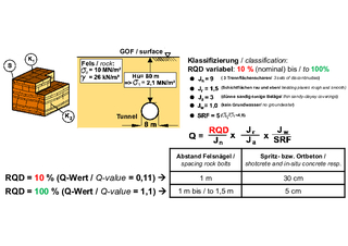 5 | Influence of the RQD index on the support recommendations according to the Q-system
Credit/Quelle: WBI GmbH
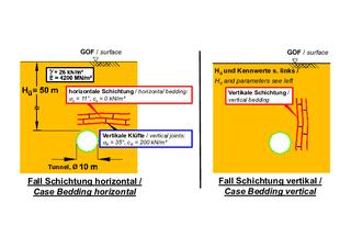 6 | Influence of the orientation of the discontinuities on the support, statement of problem
Credit/Quelle: WBI GmbH
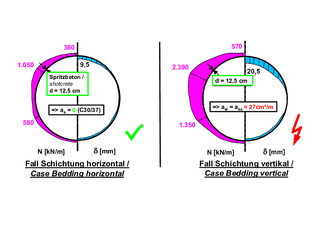 7 | Influence of the orientation of the discontinuities, result
Credit/Quelle: WBI GmbH
The effect of such a misinterpretation would be considerable when using the Q system. With otherwise identical assumptions, the example shown in Fig. 5 would result in a Q value of 0.11 for an RQD of 10, according to which anchors every meter and a sprayed concrete membrane of 30 cm thickness would be required. For RQD = 100 %, on the other hand, only 5 cm of sprayed concrete and a larger anchor grid would be sufficient according to the nomogram.
In addition to the RQD value, five other constants are used to determine the Q-value (Fig. 2, JN: number of discontinuity sets; JR: roughness; JA: form/filling of the discontonuities; JW: groundwater reduction factor; SRF: stress reduction factor). The number of discontinuity sets can be measured. All other constants must be derived from table values using qualitative descriptions. Anisotropies and the orientation of the discontinuities are not taken into account in the Q-system.
The example shown in Figure 6 demonstrates that this simplification is inadmissible. A tunnel in sedimentary rock with a diameter of 10 m and an overburden of 50 m is considered. In the example shown in Figure 6 on the left, it is assumed that the bedding parallel discontinuities are horizontal, whereas in the case shown on the right, the bedding is vertical. The other assumptions are the same in both cases.
According to the Q-System‘s support recommendation, a 12.5 cm thick sprayed concrete shell and 3.5 m long anchors installed in a 1 m x 1 m grid would be required in both cases. FE analyses using the AJRM method (see section 2) show that this recommendation is sufficient in the case of horizontal bedding, whereas the 12.5 cm thick sprayed concrete membrane would be significantly overstressed in the case of vertical bedding. In this case, a design with the safety factors of the exceptional design situation would result in a required reinforcement of ~27 cm²/m inside and outside, which cannot be installed in a 12.5 cm thick sprayed concrete membrane. In this case, a support according to the Q-system would therefore lead to failure of the support (Fig. 7). This example shows that the lack of consideration of the orientation of the discontinuities in the Q-system is not permissible and involves major risks.
RMR and RMi Systems
The above explanations have shown that the use of the Q system for tunnel planning in sedimentary rock should not be allowed and can involve major risks. As mentioned in the introduction, other classification systems have been introduced in the past.
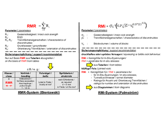 8 | Further classification systems
Credit/Quelle: WBI GmbH
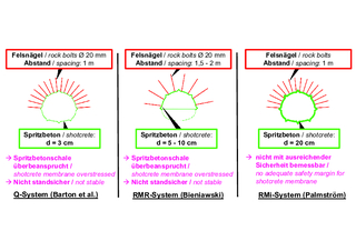 9 | Case study Österfeld Tunnel, support recommendations Q, RMR and RMi system
Credit/Quelle: WBI GmbH
Bieniawski‘s RMR system basically works in the same way as the Q system. The RMR value results from the sum of a total of six constants. Based on the RMR value, support recommendations for tunnel structures can be derived from tables (Fig. 8, left-hand side).
The RMi system is also based on empiricism. The RMi value is taken into account using a somewhat more complicated formula. Together with other parameters that can be derived from tables, support recommendations can also be determined from tables or nomograms (Fig. 8, right).
In the opinion of the authors, the use of these two systems, which will not be discussed in detail here, is also unsuitable for tunnel construction in sedimentary rock.
This statement will be illustrated using another example. This is the Österfeld Tunnel in Stuttgart, which was built many years ago and is located in the Black Jurassic [20].
The tunnel was planned and built using the AJRM method. The anisotropic deformation behavior and the reduced strength along the bedding and the joints were taken into account in the stability analyses carried out using the finite element method. The construction was accompanied by monitoring. The results of the analyses were checked on the basis of the monitoring results.
After construction, the support recommendations according to the Q system, the RMR system and the RMi system were derived for comparison. First of all, it should be noted that all three systems produce significantly different support recommendations (Fig. 9).
A comparison with the design and corresponding back analyses also have shown, that a design according to the Q-system would have led to a failure of the structure. Even according to the RMR system, the tunnel would probably have collapsed. If planning had been carried out according to the RMi system, nothing would have happened, but the required safety factors would not have been met.
4 Case Study: Trimberg Tunnel, A44 Highway
Unfortunately, despite the shortcomings described, the classification systems discussed in Section 3 have also been used in Germany in the recent past or corresponding data has been provided in expert reports. In the tunnel engineering report for the Trimberg Tunnel on the A44, information on the RMR value can be found in addition to the rock mechanical parameters. We have examined the significance of the RMR value in more detail for the tunnel section in the Netra Graben. The tunnel here has an overburden of 32 m and the RMR value specified in the above-mentioned expert report is 15 to 19.
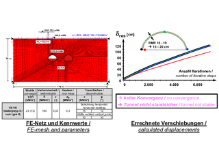 10 | Trimberg Tunnel, section in the Netra Graben, FE analyses for the construction stage of vault heading
Credit/Quelle: WBI GmbH
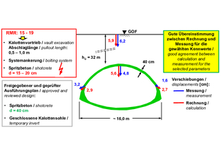 11 | Trimberg Tunnel, section in the Netra Graben, vault heading with temporary invert, comparison of the measured and predicted displacements
Credit/Quelle: WBI GmbH
For these values, the RMR system predicts that the tunnel can be excavated by vault heading with cut-off lengths of 50 cm to 1 m, with a system anchor and 15 to 20 cm of sprayed concrete (Figs. 10 & 11).
Calculations using the AJRM method (Section 2), taking into account the elastic and viscoplastic rock mass properties and the discontinuities, show that a corresponding tunnel heading would not be stable. The calculations show no convergence (Fig. 10). Instead, a vault heading with a closed invert and a 40 cm thick sprayed concrete membrane was required (Fig. 11). The application of the RMR method with the associated values in the tunnel engineering report would therefore have led to a failure. In contrast, the application of the AJRM method, taking into account adequate rock mechanical models and parameters and also corresponding calculations, led to safe and economical tunnel construction. This can also be shown by comparing the calculated (predicted) and measured displacements (Fig. 11).
5 Conclusions
The authors warn to use the so-called prescriptive measures in the form of the Q-system, the RMR system or the RMi system in tunnel planning. The inadmissible simplification of the description of rock masses and the corresponding mechanical parameters is misleading and poses major risks. When using the corresponding nomograms and tables, stability analyses are not being carried out. This is another reason why the use of these methods is not permitted in Germany under current regulations. We hope that this will continue to be the case after the introduction of the new EC 7, which is expected in the near future. It would be better for experts to continue working together to further develop the AJRM method than to invest energy in the further development of systems which, in the view of the authors of this article, are already incorrect in their basis.

