Ibbenbüren Mine Water Drainage Tunnel – Project Presentation and Experience After 24 Months
In October 2021, construction work began on the new mine water drainage tunnel (MWDT) in the area of Germany’s northernmost coal mine in Ibbenbüren, which was closed in 2018. The costly pumps of the mine water drainage system have now been switched off and the mine water is to rise to a height of +63 m NHN (= meters above standard zero) and then be discharged via the new drainage tunnel to the mine water treatment plant at the Gravenhorst site, which is also to be newly constructed. This article presents the project task and reports on the status of the planning and construction work after a construction period of 24 months. A second article is planned for the year 2025, which will then report on the further progress of construction and on experience gained from the construction work completed by then.
Inducement
Locality and Situation
 1 | Tectonic and Mining Structure of the Ibbenbüren Carboniferous Fault Block
Credit/Quelle: [1]
In the Tecklenburg region, RAG Anthrazit Ibbenbüren GmbH operated Germany’s northernmost coal mine. The site consisted of two fields: The West field, which was shut down in 1979, and the East field, which was active until the end of 2018 (Fig. 1). Starting in 1979, the planned rise of mine water in the West field – i.e., groundwater rising through the soil along the rock layers and fissures, penetrating the mine structure and dissolving minerals from the rock, mainly salts, but also iron – took place. This rise lasted until 1982. Since reaching the level of +65 m NHN, the mine water from the West field has been channelled through the Dickenberg adit via the adit ditch into the existing Gravenhorst mine water treatment plant (AzGA) and drained further into the Hörsteler Aa river.
In the mine water treatment plant, iron precipitation is carried out by aeration and neutralization using milk of lime, followed by sedimentation. Mine water from the East field, which was active until the end of 2018, was discharged via the Oeynhausen shafts and the Ibbenbüren headings to the sedimentation ponds in Püsselbüren. This was followed by discharge into the Ibbenbürener Aa. The plans in the framework of the closure of the Ibbenbüren mine envisaged the start of the rise in mine water from the end of 2019. From 2025, the mine water is to be collected at the level of +63 m NHN and fed to the new Gravenhorst mine water treatment plant via the new drainage tunnel which is to be built with a precast segmental tunnel lining. To ensure the level without backwater over the entire length of the approx. 7.2 km long new drainage tunnel, the lining of the tunnel will be designed to drain via planned penetrations in combination with a water-permeable backfill [1], [2].
Purpose
The pumps used for dewatering at the Ibbenbüren mine consumed the electricity of an average of 12 900 households during the operating phase. Since 2019, the pumps have no longer been used, resulting in significant energy savings and a reduction in CO2 emissions. After the mine water has risen to +63 m NHN, the water must be collected and discharged by the mine water drainage tunnel.
Operating Principle
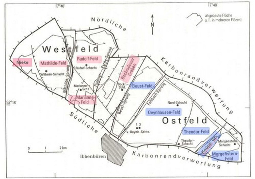
Due to the topographical conditions, it is possible for the drainage tunnel to emerge from the ground at +63 m NHN in the west, and the water can then be channelled to the new AzGA to be built in Gravenhorst (Fig. 2).
The mine water drainage tunnel itself has a minimal gradient from west to east as far as Shaft 1 (von Oeynhausen Shaft) so that the mine water entering the drainage tunnel can flow by gravity from Shaft 1 to the new western end of the tunnel via the outlet structure into the adit trench and further in the channel to the AzGA. Since the waters of the West field and the East field have different mineralization, the drainage tunnel has two separate channels so that treatment in the AzGA can also be optimized for the different waters.
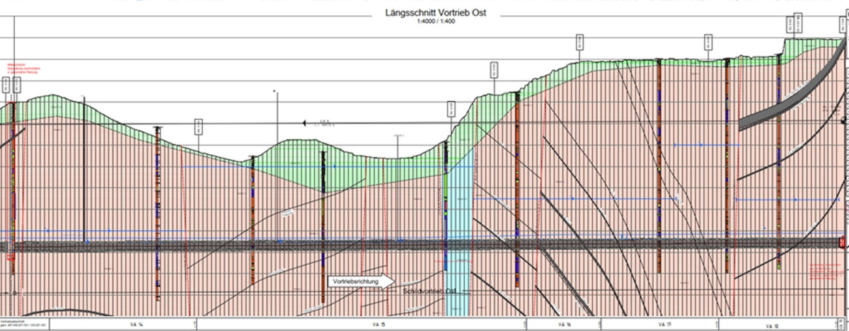
 2 | Longitudinal section through the west and east fields for planned mine water rise
Credit/Quelle: [3]
Project Participants
The client of the project is RAG Aktiengesellschaft in Essen, represented by the Ibbenbüren division. The design planning as well as parts of the construction planning were carried out by ARGE Grubenwasserkanal Ibbenbüren, consisting of the engineering offices Dorsch International Consultants GmbH, IMM Maidl & Maidl GmbH & Co. KG and Dr. Pecher AG. This joint venture is also responsible for site management and construction supervision during execution. The subsoil expertise was prepared by Ingenieurgesellschaft Dr. Spang. The contract for the geotechnical site management during the construction phase was awarded to Ahlenberg Ingenieure. ZPP Ingenieure AG was engaged as inspection engineers.
In October 2021, the contract was awarded to the joint venture Wayss & Freytag Ingenieurbau AG/Züblin AG after successful completion of the pre-qualification and the bidding competition for the construction of the new Ibbenbüren mine water drainage tunnel. The contractor is the joint venture ARGE Tunnel Ibbenbüren (ATI). Maidl Tunnel Consult was contracted by ATI as the designer for the tunnel lining as well as the face pressure calculations. The Technical Department of Züblin provided the temporary works design for the tunnels. The remaining design services will be provided by ARGE Grubenwasserkanal. The construction material technology department of Wayss & Freytag is responsible for the design of the tail void filling material.
The Mine Water Drainage Tunnel
Alignment and Gradient
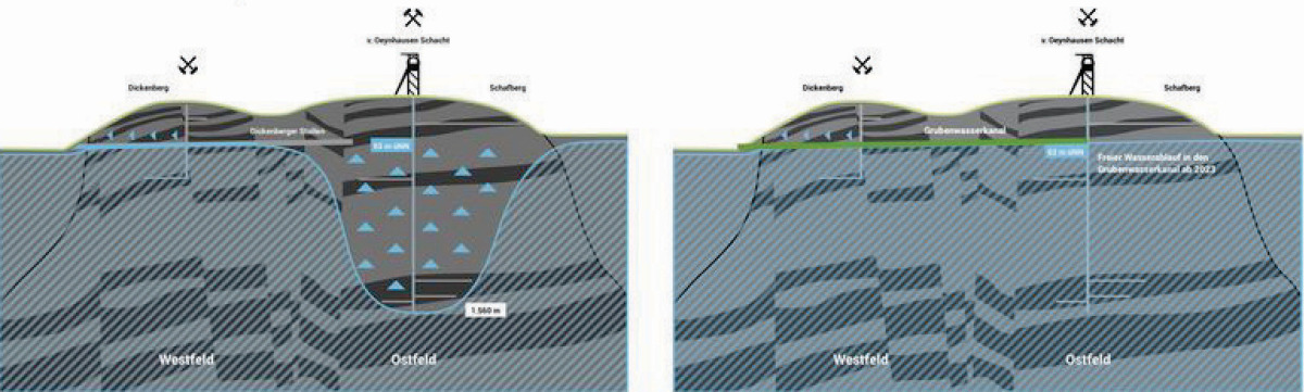
The alignment of the drainage tunnel to be constructed (Fig. 3) runs in the direction of flow from east to west over a length of approx. 6 km, beginning with the connection to the mine complex at von Oeynhausen Shaft 1 in a northwesterly direction and then bends off in a southwesterly direction to the outlet at the Stollenbach stream. The drainage tunnel, which is to be driven by mechanized tunnelling, follows the course of the existing Dickenberg adit and has a total length of about 7138 m, divided into the west (3244 m) and east (3894 m) sections. Together with the approx. 260 m of tunnel in open construction, this results in a total length of 7398 m. The gradient of the tunnel varies from west to east between 0.05% and 0.25%. The overburden of the tunnel is just under 100 m at shaft 1 and approx. 7 m at the outlet structure.
 3 | Overview of mine water drainage tunnel between shaft 1 (east) and outlet structure Stollenbach (west)
Credit/Quelle: [1]
Geology/Hydrogeology
The project area lies predominantly on the Ibbenbüren Carboniferous Plateau, which due to its formation forms a plateau within the Münsterland Cretaceous Basin and the North German Plain. The maximum ground elevation is approx. 152 m NHN near shaft 1 and the lowest ground elevations of approx. 61 m NHN are in the area of the planned outlet shaft. According to the subsoil report, the following soils are to be expected in the area of the drainage tunnel: topsoil (layer 1.1), fill (layer 1.2), Quaternary (layer 2.1 aeolian sand, layer 2.2 solifluction deposits ans layer 2.3 ground moraine), Muschelkalk (layer 3.1), Zechstein (layer 3.2) as well as Upper Carboniferous of the Ibbenbürener layers (layer 4).
The launch pit west is located in layers 2 and 3.1. In the area of the central shaft (launch pit for the east drive), layers 1, 2 and 4 have been identified. With the exception of the first 460 m of the west drive (layer 3.1) and a forecast short section of the east drive (layer 3.2), the alignment of the mine water drainage tunnel lies in the bedrock of the Ibbenbürener layers (layer 4), which according to the geotechnical report show Cerchar values of 0.3 (slightly abrasive) to 5.5 (extremely abrasive). The construction water level is between 1.60 m and 5.0 m above the tunnel crown for the west drive and between 5.0 m and just under 45 m above the tunnel crown for the east drive.
The launch pit west is located in layers 2 and 3.1. In the area of the central shaft (launch pit for the east drive), layers 1, 2 and 4 have been explored. With the exception of the first 460 m of the west drive (layer 3.1) and a forecast short section of the east drive (layer 3.2), the alignment of the mine water drainage tunnel lies in the bedrock of the Ibbenbüren strata (layer 4), which according to the geotechnical report show Cerchar values of 0.3 (slightly abrasive) to 5.5 (extremely abrasive). The construction water level is between 1.60 m and 5.0 m above the tunnel crown for the west drive and between 5.0 m and just under 45 m above the tunnel crown for the east drive.
Overview of Structures
The overall structure of the Ibbenbüren mine water drainage tunnel to be constructed consists of the following briefly described partial structures, from west to east [1]:
West outlet structure: at the western end at the transition to the Stollenbach stream, the so-called outlet structure is to be constructed. This connects to an uncovered drain with a length of about 260m. This section consists of an excavation pit with secant bored piles and DN 3600 sewer pipes laid in open cut trenches. The start shaft for the west tunnel drive is located to the east.
Launching shaft: The start shaft is also to be constructed with a bored pile wall, around 10 m deep, 30 m long and 10 m wide. The shoring walls are supported by anchors, and in the upper area by pipe braces and a steel frame in the area of the entry wall.
West drainage tunnel: The west tunnel drive begins at the starting shaft and ends at the center shaft at a constant gradient. Its length is approx. 3244 m, its inside diameter is 3.60 m, and its single-shell segment lining is 45 cm thick. This results in an outside diameter of 4.50 m. At the beginning, the overburden is approx. 7 m above the tunnel crown and increases to approx. 65 m towards the center shaft.
The cross-section of the tunnel structure (Fig. 4) is determined, among other things, by the hydraulic requirements (e.g. separate drainage of the mine water in the west and east channels), operational necessities (rescue route, maintenance vehicle route) and the requirements during construction of the tunnel. Depending on the area, the annular gap produced during mechanized driving must either be grouted or filled with pea gravel as a drainage measure.
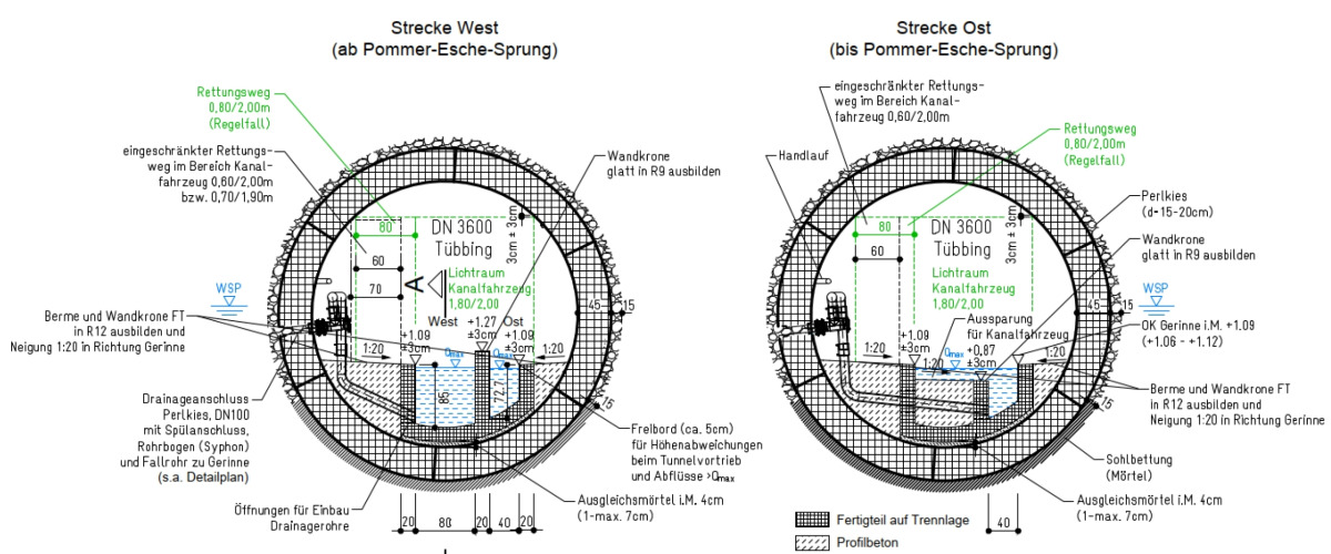 4 | Tunnel cross-section according to tender for west and east tunnel
Credit/Quelle: [1]
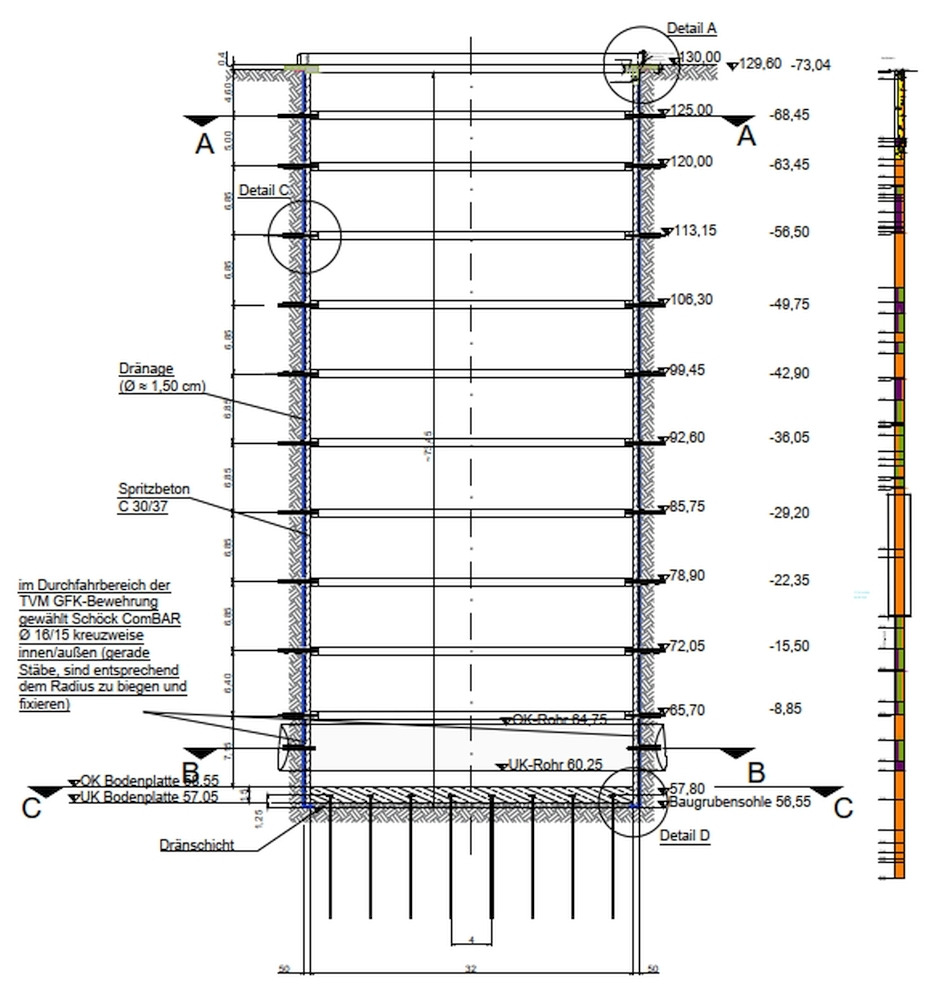
Central/intermediate shaft: The new central/intermediate shaft, which is to be excavated to a depth of around 70 m, is located approximately in the middle of the drainage tunnel in the area of the Bockradener Graben. The excavation pit has a circular cross-section with an excavation diameter of 32.6 m, which is mainly due to the logistical requirements resulting from tunnel driving. The upper section of the shaft is located up to approx. 10 m below ground level in unconsolidated rock, which consists partly of minestone. Loosening and conveying of the soil in the area of the backfill is planned by means of an excavator, if necessary with a chisel attachment. In the area of the solid rock in the Upper Carboniferous, the rock can be loosened most economically by means of drilling and blasting (loosening blasting), according to the assessment of the subsoil expert. The material is loaded and conveyed by chain excavators at the bottom of the excavation pit, salvage containers and a gantry crane that can be moved over the shaft.
 5 | Central shaft (excavation pit and final structure)
Credit/Quelle: [1]
The excavation support is designed with a reinforced, 50 cm thick sprayed concrete lining, which is not foreseen to be impermeable to pressurized water (installation of dimpled sheeting and drainage). The sprayed concrete lining is to be reinforced by an in-situ concrete head beam at ground level. In the course of the further excavation, so-called bracing rings (approx. 80 x 80 cm) are to be installed, which are to be arranged at a distance of just under 7 m. Vertical loads from the sprayed concrete lining are to be taken up at the level of each bracing ring by means of cantilevers. Between -60 m and -75 m below ground level, sealing bodies must be created by curtain injection due to the fracturing. In the entry area for the west TBM and for the start of the east TBM, the curtain injections have been further compacted and extended.
The base of the excavation pit is a 50 cm thick reinforced concrete base. An underlying drainage layer of gravel with built-in pump sumps allows open residual water drainage for the excavation pit in order to relieve the concrete base from the existing groundwater pressure.
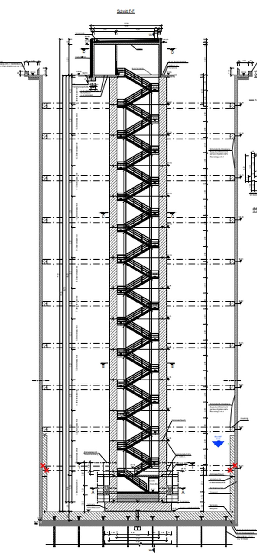
After completion of the west and east tunnelling work, a rectangular shaft structure (6.80 m x 8.30 m) is to be built in the excavation pit to provide access to the drainage tunnel, to act as an escape and rescue route, to discharge the exhaust air from the drainage tunnel and to serve as an installation site for control equipment (Fig. 5). The space between the shaft structure and the excavation shoring must be backfilled after completion of the shaft work.
East drainage tunnel: The east tunnel drive begins in the aforementioned central shaft and ends with a slight incline in a reception cavern at shaft 1 under the mine site. The length of the east tunnel is approx. 3894 m. The dimensions of the segment lining are identical to those of the west section (Fig. 4), with the overburden here increasing from around 65 m at the central shaft to just under 100 m at shaft 1. After the tunnel boring machine has been dismantled in the reception cavern (the shield skin remains in the ground), an in-situ concrete lining is to be constructed between the last tunnel ring and shaft 1 and the invert channel has to be installed (Fig. 4, right cross-section).
Production of discrete connections and interior lining: Since the mine water has to be led into the interior of the tunnel not only along the tunnel tube via the installed pea gravel, but also discretely via water-bearing individual tributaries, the known locations, in particular the adjacent water-filled exploited sections in the route area and the Dickenberg adit, are to be connected directly after excavation of the MWDT.
The connection is made via boreholes from the tunnel. The boreholes are to be drilled prior to installation of the invert channel and the drainage pipes installed in the MWDT. The boreholes will be sealed against water ingress during construction. The closure will be removed only after the channel is installed in the MWDT and the receiving water is secured via the outlet channel and the outlet structure. The design of the invert channels to be installed in the east and west tunnels is shown in Fig. 4.
Shaft 1 (formerly also called von Oeynhausen shaft): This shaft, located on the RAG Anthrazit premises in Ibbenbüren, is the connection to the drainage tunnel, as the dewatering systems built into the East field mine structure end here. Previously, the pumping systems lowered the mine water level by conveying it to the Ibbenbüren headings, which begin at shaft 1 at 85 m NHN. Shaft 1 has an inside diameter of 4.40 m, partly lined with steel segments, partly with sandstone masonry, and is now still 100 m deep (bottom level of the mine water drainage tunnel). Below this level, in preparation for the closure of the mine, the shaft was sealed with a concrete partition over a length of 100 m. This contains steel pipes through which the rising mine water later enters the drainage tunnel. At the level of the drainage tunnel, the reception cavern for the arrival of the TBM east has already been constructed as preliminary construction works.
Construction Schedule 2021–2025
The milestones set out in the contract and the Client's envisaged construction programme including the planned execution periods are listed below.
Contract deadlines
Start of construction work: 4 weeks after award of contract
Partial commissioning of both invert channels: 37 months after award of contract
Completion of the entire construction project: 43 months after award of contract
Construction programme and associated time periods
Start of construction work: 11/2021
Outlet structure and launch shaft (construction pit and lining): 12/2021–10/2024
West tunnel structural work: 11/2022–12/2023
Central shaft (excavation and lining): 11/2022–04/2025
East tunnel structural work: 01/2022–01/2024
Interior lining with invert channel and discrete connections: 01/2024–11/2024
Shaft 1 (removing of fixtures and lining): 08/2023–03/2025
Special Aspects of Approval
The Ibbenbüren mine water drainage tunnel project is being implemented in compliance with mining law. The responsible supervisory and approval authority is the Arnsberg District Government (BRA), Dept. 6 Mining and Energy in North Rhine-Westphalia. The construction of the drainage tunnel has been authorized with the approval of the final operating plan for the Ibbenbüren mine. During construction, numerous supplementary operating plans have to be submitted to the BRA via RAG and approved. These applications must take into account the safety requirements and specifications from the mining guidelines and regulations, e.g. in the design of pipelines and cable routes in shafts and ventilation in headings. Compliance with the ancillary provisions/conditions of the individual approvals is closely monitored by representatives of the authorities and the client.
Status of Construction Work & Technical Details
West Outlet Structure/Start Shaft
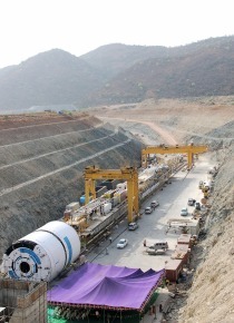
For the construction of the west outlet structure, DN 3600 precast reinforced concrete pipes were laid over a length of approx. 260 m using the cut-and-cover method. On the eastern side of the outlet structure, there is an approx. 30 m long launch pit. The shoring, consisting of secant bored piles with a diameter of 1.20 m, is tied back laterally in three layers and braced in the upper area against the head beam (Fig. 6). GRP-reinforced bored piles were used in the drive-through area of the TBM.
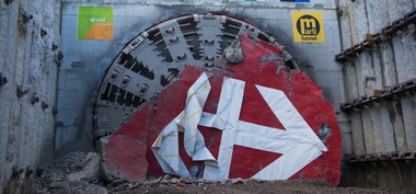
 6 | Start shaft at the west outlet structure with TBM during assembly
Credit/Quelle: ATI
Excavation – West Tunnel
The tunnels are to be excavated mechanically by means of TBM drives. The core components and functionalities here are the conveyor system from the excavation chamber to the shield area using a screw conveyor and the transfer to a hydraulic conveyor circuit to the surface. Depending on the rock mass, the method variants that can be set here must allow for open excavation, compressed air-supported excavation as well as material- or fluid-supported excavation.
Furthermore, with regard to mine gas and coal dust, an “encapsulated” drive, i.e. full filling/humidification at the face – hydraulic muck transport system to above ground (hydraulic circuit analogous to mix/hydro shield), is basically required. The further machine equipment must include, among other things, advance exploration possibilities (gas detection and solution) and advance ground improvement measures as well as water collection and drainage through, among other things, openings in the excavation chamber with connections for pipelines/pumps in order to drain areas with water ingress in advance/temporarily. The machine technology specified by the client was classified as a Variable Density Shield (VDS) in accordance with the DAUB recommendation (2020) and was also offered in this way by the joint venture as part of the bidding competition.
Due to the local ground conditions, including the prevailing rock and fracture water pressures of up to approx. 4.5 bar, as well as the technical project requirements, the two TBMs are to be operated in different tunnelling modes (VTM). According to the tender, these are the modes VTM 1, VTM 2 and VTM 3, whose specific characteristics and areas of application are listed in the table in Fig. 7.
For the west drive, the following specifications had to be implemented, resulting from the geological conditions, the location of the exploited sections of the Ibbenbüren mine (e.g. Dickenberger adit, “Glückburg West”, “Glücksburg East” and “Buchholz” exploited sections) as well as the utilisation requirements of the drainage tunnel.
From the starting shaft onwards, the first approximately 480 metres of the tunnel will be driven in VTM 1 mode, with complete grout injection and undrained. For the rest of the route, the open tunnelling mode VTM 2 with drainage measures, i.e. with pea gravel injection, was basically planned. The VTM 1 and VTM 3 tunnelling modes could be considered as a fallback level at any time. Every 100 m, sealing rings must be built over four rings to prevent the mine water from flowing along the tunnel and not into the tunnel via the openings. For this purpose, the excavation is to be carried out with the VTM 1 with complete grout injection. Furthermore, full mortar grouting is to be carried out in areas where the tunnel passes over or under the former mine tunnels.
When entering the area of the central shaft, which is sealed by means of an injection curtain, the driving mode must be changed to VTM 1 again for a distance of approx. 12 m, so that the driving does not cause any water pathways along the shield track to the central shaft.
Segmental Lining/Segment Design
The detailed design of the tunnel lining is contractually owed by the contractor. Based on the client's specifications with regard to the minimum lining thickness of the segment as well as the drainage and backfilling concept, the joint venture has worked out the following segment design together with its planner MTC. A six-part uni-ring (Fig. 8) with a large keystone, an inner diameter of 3.60 m and a lining thickness of 45 cm is used. The outer diameter results in 4.50 m. The ring width was optimised to 1.30 m.
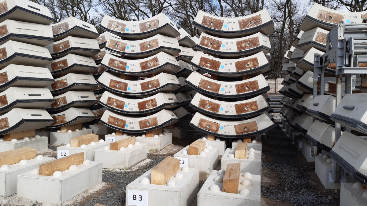 8 | Segmental lining MWDT Ibbenbüren
Credit/Quelle: ATI
Due to the requirements for the tail void filling with pea gravel or full mortar/sealing rings, four different equipment types of the segments are used. The coupling of the rings to each other is done by friction, whereby an intermediate material made of hard fibre is glued into the flat ring joints. Welded reinforcement cages are used. The concrete grade is a C50/60 with exposure classes XC4, XA3, XF1, WA.
The static dimensioning had to take into account not only the construction loads from the TBM and the handling, but also the changing bedding conditions caused by the annular gap filling with pea gravel or with mortar, the respective rock loads and the different water levels as well as temperature load cases. The fire load case did not have to be verified.
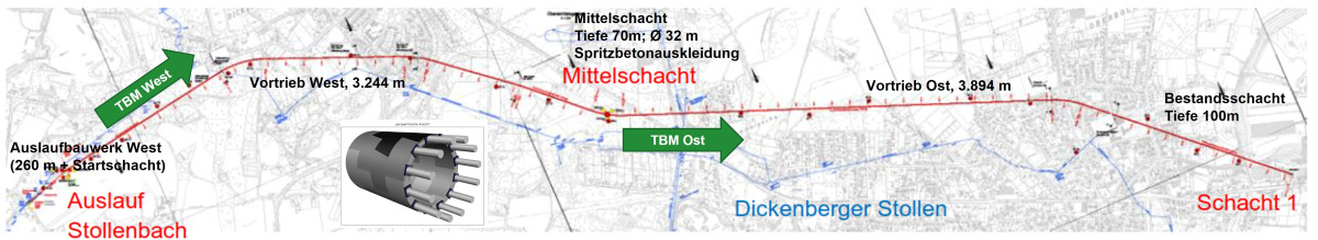
TBM Design/Concept
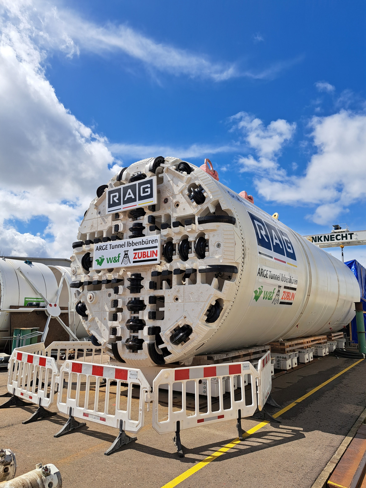 9 | Factory acceptance of the TBM West
Credit/Quelle: Herrenknecht
A particular challenge for a variable density TBM (VDS TBM) arises here from the small dimensions of the tunnel. Previous experience with VDS machines only existed for diameters > 8.0 m. Accommodating the entire process technology in a tunnelling system with a bore diameter of just 4.80 m and an inner tunnel diameter of only 3.60 m posed a particular challenge here. Furthermore, the regulations resulting from the applicable mining law created additional challenges.
A Herrenknecht TBM, type VDS, with a bore diameter of approx. 4.80 m and a shield length of slightly less than 16 m (Fig. 9) was used. The total length of the TBM consisting of 20 back-ups is almost 220 m. The TBM is supplied via track-bound logistics.
 10 | TBM West assembled in the shaft
Credit/Quelle: ATI
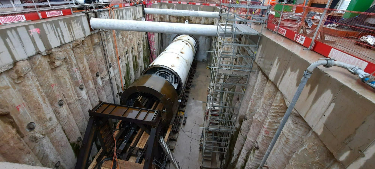
Assembly Concept and Launch TBM West
The previously described dimensions of the launch shaft, which has a length of only approx. 30 m, do not allow for a complete assembly of the entire tunnelling system prior to the TBM launch. Furthermore, if a classic start-up construction with thrust frame and blind rings had been used, there would have been hardly any more space for the logistical supply with the shield length of just under 16 m, as long as the blind rings had not been dismantled. For this reason, ATI decided on a launch system without blind rings with a moving thrust frame which stands against the end wall after the shield has completely entered the ground (Fig. 10).
The attachment of the other back-ups, which were pre-assembled on the site installation area, was then carried out in packages. As soon as two more back-ups had disappeared in the excavated tunnel, the next two were lowered into the shaft, attached, and driving started again. After the assembly of the entire tunnelling system was completed, the shaft bottom was then converted for tandard tunnelling and logistics operations, and the rear stiffening construction was also dismantled during this process.
Experiences From the First 1000 m of the West Drive
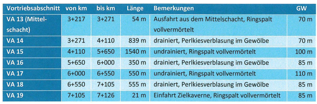
The calculations of support pressure and grout injection pressure were carried out by the ATI planner MTC Tunnelconsultants, as was the segment lining. For the western tunnel drive (Fig. 11), the client's specifications resulted in 13 drive sections, which were to be alternately drained or fully grouted in the respective modes. The table in Fig. 12 shows examples of the characteristic values and features of the 13 drive sections.
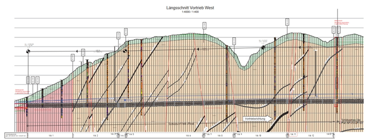 11 | Excerpt from excavation plan west
Credit/Quelle: MTC
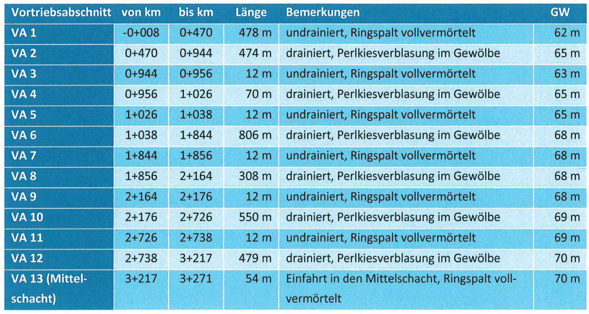 12 | Driving sections and groundwater level in m NHN, west drive
Credit/Quelle: MTC
The driving boundary conditions during the excavation of the first 1000 m were quite varied in detail and already challenged the versatility of the TBM several times. For example, in drive section 1 (VA 1), the TBM drove through areas with cutting wheel clogging and at another point a sudden loss of support fluid occurred due to the fracturing of the rock.
Due to the geological conditions encountered, the cutting wheel checks could be carried out under atmospheric conditions. Tool wear of the cutting wheel could practically not be detected in VA 1.
The transition between VA 1 and VA 2 was fluid. In contrast to VA 1, the geology in VA 2 tends to be very abrasive, with the consequence of high wear within an excavation distance of 250–500 m.
The Dickenberg adit, which was built in 1771 and crosses the tunnel route with a minimum overburden of 1.50 m, has already been successfully traversed.
The exit and entry into the approx. 70 m deep central shaft take place under the protection of the sealing curtain injections carried out previously.. When entering the shaft, the ongoing driving work of the east drive must be taken into account. This also applies to the subsequent dismantling of the TBM via the central shaft and backwards via the start shaft at the west outlet structure.
Central Shaft
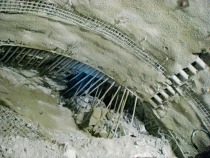
 13 | Excavation pit shoring central shaft
Credit/Quelle: [1]
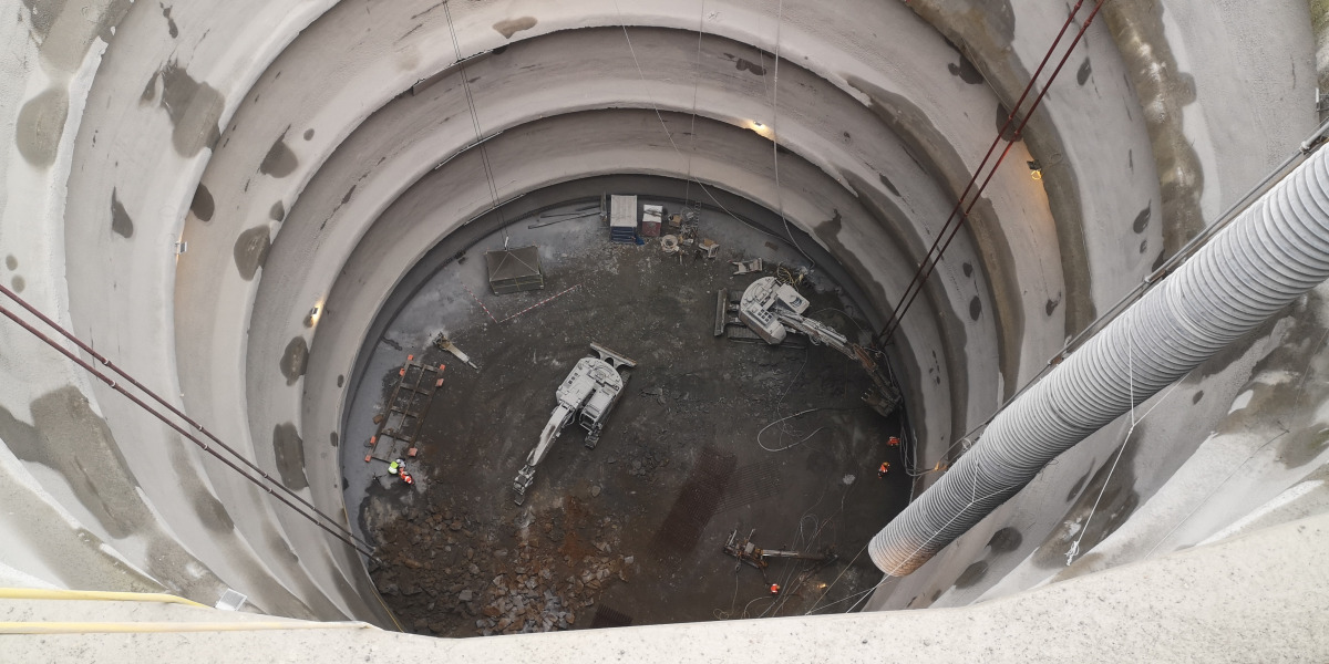
At the shaft head, due to an almost 10 m thick deposit of anthropogenic material, an embanked excavation pit was first constructed up to 5.8 m below the surface as well as a 1.5 m deep trench, which had to be secured with reinforced sprayed concrete. Afterwards, a 50 cm thick and 6.5 m high angular retaining wall was built in-situ, including fall protection. After its completion, the shaft was successively sunk by means of an excavator and secured with 50 cm thick, three-layer reinforced sprayed concrete (in the entry and exit areas with GRP reinforcement) in accordance with the tender (Fig. 13). A 40-tonne excavator, an 18-tonne excavator and a dump bucket were used, in which the excavated material was transported to the ground surface by means of a gantry crane.
The special requirements resulting from the applicable mining law had to be taken into account for the shaft installation and the sinking process. In addition, the aforementioned bracing rings were installed at the specified depths.
The timing of the sinking and securing process (Fig. 14) was further optimised by using cycle planning according to lean principles (Fig. 15), thus significantly improving the sinking performance. Conveying rates of up to 400 m³/day could be achieved.
 14 | Sinking and securing of the central shaft
Credit/Quelle: ATI
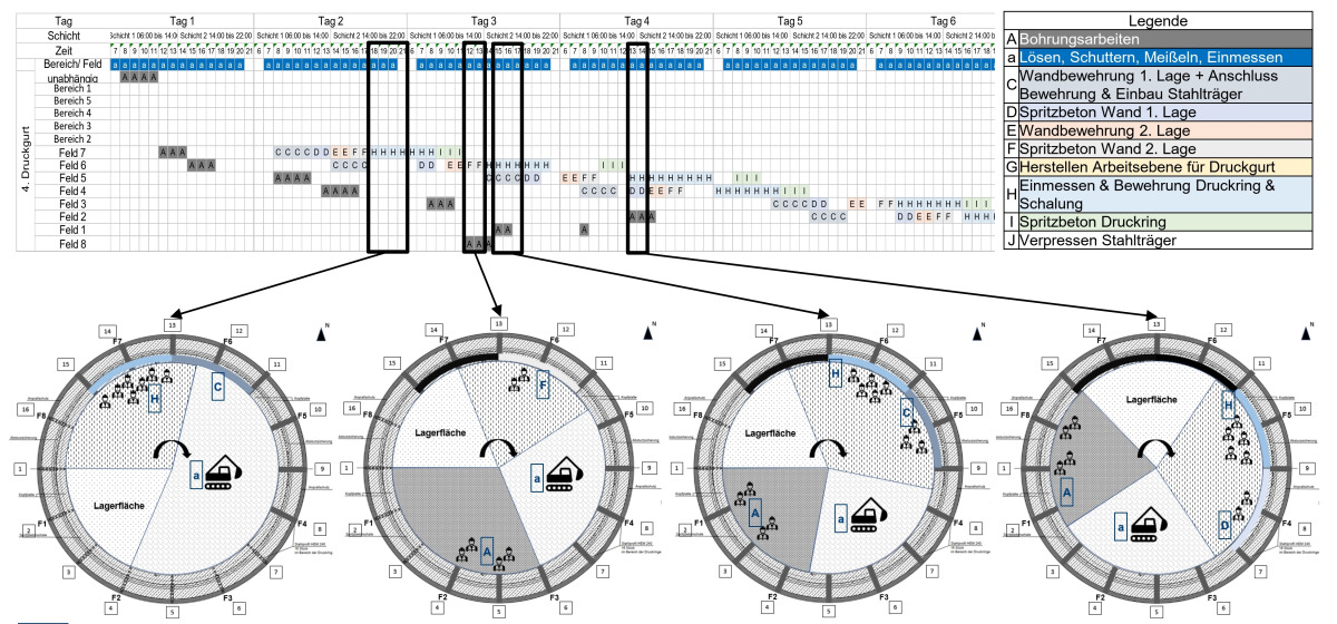 15 | Lean cycle planning
Credit/Quelle: W&F Ingenieurbau AG
A total of 64 fans, each with five boreholes, were drilled as curtain injections to reduce the water inflow and as sealing blocks for the entry and exit of the two TBMs in the partly very fissured ground at level -60 m, before the shaft was brought to its final depth and the 50 cm thick reinforced concrete base was laid on a drainage layer of gravel.
Preparation for East Drive/West TBM Entry
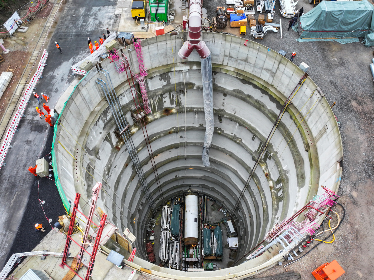
After completion of the shaft bottom, assembly of the auxiliary construction structures for the start-up of the TBM East and the associated shaft installations began immediately. The TBM East was then installed on the shield cradle. The start-up procedure is similar to the west drive, but the specific shaft dimensions have to be taken into account accordingly. For example, due to the shaft depth, in contrast to the start-up of the TBM West, all the central back-up units are already at the bottom of the shaft. Due to the cramped conditions, the back-up units are temporarily arranged one above the other (Fig. 16).
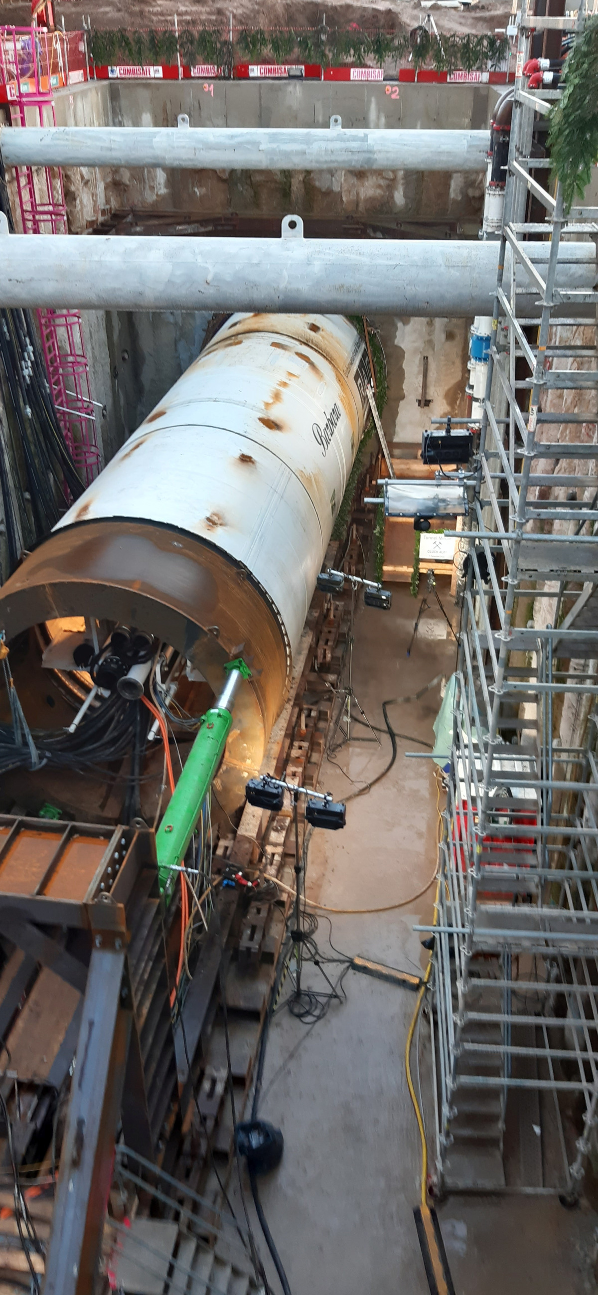
 16 | View into the central shaft with TBM East shortly before the start-up
Credit/Quelle: RAG
In the arrival situation, the TBM from the west drive enters the central shaft through the GRP-reinforced sprayed concrete lining onto a steel shield cradle and is dismantled in the 70 m deep excavation pit. At this point, the east drive is still in progress, and the supply to the east drive must also be guaranteed during the dismantling of the TBM West.
The back-up and advance installations can be dismantled and transported away at the rear via the west launch pit. The tracks for the transport train remain in place for the following channel and berm construction and are only to be taken up in the course of the interior construction (setting of the prefabricated channel parts and concreting of the berms).
TBM Drive East
For the east drive, a TBM of almost the same design as for the west drive will be used. Here, too, it is a VDS TBM with a bore diameter of 4.80 m. Similar to the west tunnel, there are also detailed specifications for the east tunnel with regard to the driving modes to be used and the annular gap backfill. The east tunnel, too, has to pass over/under various drifts and fault zones, including, including the Pommer-Esche-Sprung, the Bockradener Graben and the Fahlbach and Beust-Sprung.
Again, the heading is divided into alternating sections of full grout, pea gravel, and sealing rings. The excavation ends in the reception cavern at Shaft 1 (Figs. 17 & 18).
 17 | Driving sections and groundwater level in m NHN, east drive
Credit/Quelle: MTC
 18 | Excerpt from driving plan east
Credit/Quelle: MTC
A particular challenge for the east drive is certainly the supply of material to the drive via the 70 m deep central shaft. This was of particular importance in the conceptual design of logistics, material supply and disposal, and the safety concept. In developing the logistics concept, the focus was on avoiding "just-in-time" lifts by the gantry crane. Crane cycles from the site surface to the supply train, for example, would take up too much time for continuously efficient logistics. The preloading of a complete second train is also not possible due to the shaft diameter and the small inner tunnel diameter. In addition, the parallel entry of the TBM West into the central shaft and its dismantling during the ongoing driving work East is also a special challenge. Thus, the complete logistics areas at the bottom of the shaft had to be planned around the exit path of the TBM West that would be required later.
The resulting hydrostatic pressure at a shaft depth of more than 70 m poses a challenge to all supply systems (in particular the feed and conveying circuits) to be able to safely reduce any pressure peaks that may occur as a result of a system failure. In addition, the material conveyed in the riser must not lead to blockages at the bottom of the shaft in the event of a system failure. For this purpose, Herrenknecht AG in cooperation with ATI, has developed an intelligent circulation system with numerous safety precautions.
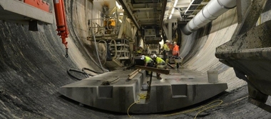
Discrete Connections and Channel Installation
Following the construction of the tunnel and the boreholes from the tunnel, the interior work of the mine water drainage tunnel has to be carried out with installation of the channel, the berms and the connecting pipes for the drainages and discrete connections. This will be done in reverse, from east to west, separately in the two sections of the west and east drives. A trailing machine train is used for this purpose, which enables the berm concrete, the installation of the prefabricated channel parts and the removal of the track to be carried out simultaneously and independently of each other.
The machine train consists of a 2-track station running on the tunnel track, a gantry crane area for moving the precast elements and a concreting area for the in-situ concrete of the berms.
Shaft 1
This shaft will remain open as an access shaft to the drainage tunnel for maintenance work etc. even after completion of the construction work. For this reason, it will be provided with a new concrete inner lining and an access system. The inner lining is to be constructed using the slipforming method. Prior to this, existing installations in the shaft will be dismantled, electrical and monitoring cables will be relocated and the existing lining will be prepared for the installation of the inner lining.
Outlook 2023–2025
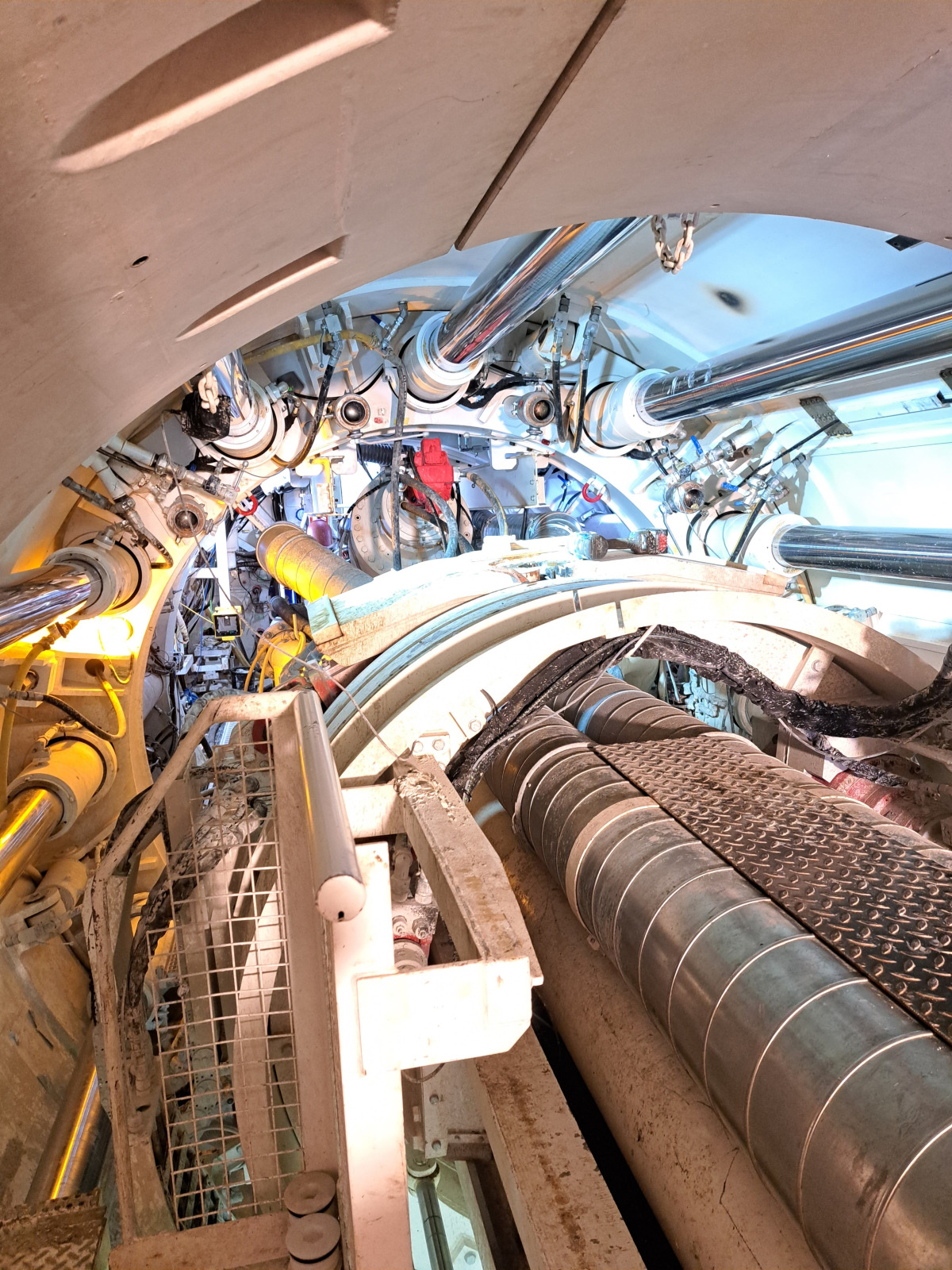 19 | Inside view of TBM West
Credit/Quelle: ATI
Excavation of the west tunnel (Fig. 19), which was started first, passed the 1000 m mark at the beginning of September 2023. This means that about one third of the 3.2 km long west tunnel has been excavated. Completion of this tunnel section with entry into the central shaft is scheduled for the second quarter of 2024.
Driving of the east tunnel began in September 2023 and is scheduled for completion by August 2024. After entry of the west TBM into the central shaft and dismantling of the tunnel boring machine, equipping of the west tunnel with the channel precast elements will begin. The prefabricated channel parts were designed by the contracting joint venture to be fitted with a modified coupling system and a seal similar to those used in segmental lining.
While the east tunnel is being driven, the inner lining is being installed in shaft 1 so that this work will be completed by the time the east TBM enters the prepared reception cavern. Following the east drive, the installation of the channel will also take place here. Construction of the shaft tower in the central shaft is taking place while the channel is being installed in the east tunnel, requiring extensive logistical measures to be taken here. Partial commissioning of the two invert channels is planned for Q2 2025, with overall completion scheduled for late 2025.
In a planned follow-up article, we will report on the experience gained on both drives, present the machine train for installing the channel, and explain the logistical challenges in the course of the lining work in the shafts and in the tunnel.